background image


5


www.eksmaoptics.com 


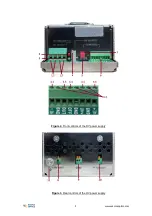
Figure 2.

 Front controls of the HV power supply 


Figure 3.

 Rear controls of the HV power supply 

Summary of Contents for HV-170-1.8

Page 1: ...HIGH VOLTAGE POWER SUPPLIES HV 170 HV2 85 Technical Description Rev 2202 2022 Lithuania ...

Page 2: ......

Page 3: ... 1 2 Main Components 2 2 2 TECHNICAL SPECIFICATIONS 3 CHAPTER 3 DEVICE LAYOUT 4 CHAPTER 4 SAFETY 7 CHAPTER 5 QUICK START GUIDE 8 5 1 GROUND THE HV POWER SUPPLY 8 5 2 SHORT TOGETHER PIN OFF 6 4 AND GND 6 2 8 5 3 SUPPLY 24V POWER 8 5 4 SET REQUIRED OUTPUT HV 8 5 5 CONNECT THE LOAD 8 5 6 SWITCH POWER SUPPLY 9 CHAPTER 6 CONTROL VIA CAN 10 6 1 CAN 10 CHAPTER 7 CAN BROWSER SETTINGS 11 ...

Page 4: ... 5 FIGURE 3 REAR CONTROLS OF THE HV POWER SUPPLY 5 FIGURE 4 ON OFF INPUT INTERNAL LAYOUT 8 FIGURE 5 CAN USB CONVERTER 10 LIST OF TABLES TABLE 1 MODELS 2 TABLE 2 MAIN COMPONENTS 2 TABLE 3 TECHNICAL SPECIFICATIONS 3 TABLE 4 CONTROLS AND CONNECTIONS OF THE HV POWER SUPPLY 6 TABLE 5 BASIC CAN BROWSER SETTINGS 11 TABLE 6 ADVANCED CAN BROWSER REGISTERS 11 ...

Page 5: ...s into validity since the shipment date Any evidence of improper use or unauthorized repair attempts voids the warranty For service warranty requests please contact EKSMA OPTICS UAB c o EKSMA Optics UAB Dvarcioniu st 2B LT 10233 Vilnius Lithuania Phone Fax E mail Website 370 5 272 99 00 370 5 272 92 99 info eksmaoptics com www eksmaoptics com ...

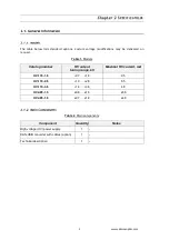
Page 6: ...equest Table 1 Models Catalog number HV output tuning range kV Maximal HV current mA HV 170 1 8 0 7 1 8 95 HV 170 2 6 1 0 2 6 65 HV 170 3 6 1 4 3 6 48 HV2 85 1 5 0 6 1 5 56 HV2 85 1 8 0 7 1 8 48 Table 2 Main components Component Quantity Notes High voltage HV power supply 1 CAN USB converter with cables option 1 Technical description 1 ...

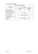
Page 7: ...y Positive Bipolar Maximum HV output power at maximal output voltage W 170 2 85 Supply voltage DC requirements 23 5 26 V 8 3 A Output voltage ripple 0 5 Output voltage control CAN Internal potentiometer Maximum ambient temperature for operation C 45 Dimensions mm 152x80x58 see Figure 1 for details Weight g 530 ...

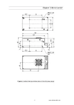
Page 8: ...4 www eksmaoptics com Chapter 3 DEVICE LAYOUT Figure 1 Outline drawing and dimensions of the HV power supply ...

Page 9: ...5 www eksmaoptics com Figure 2 Front controls of the HV power supply Figure 3 Rear controls of the HV power supply ...

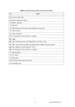
Page 10: ...er control mode 5 CAN connector 6 Control connector 6 1 Ih test point for HV current 1V 100mA 6 2 GND 6 3 OUT indication point for HV output HV off 5V HV on 0V 6 4 OFF control input to enable HV output connect to GND to allow HV output 6 5 Uhv test point for HV output 1V 1kV 6 6 Ih test point for HV current 1V 100mA 7 CAN terminator 8 HV output 9 GND output 10 HV output HV output for HV 170 11 Gro...

Page 11: ... dry non conductive POLLUTTION occurs Warning The safety of the system incorporating driver and HV power supply is the responsibility of the assembler of the system Operating the power supply is allowed to persons acquainted with the operation manual and having permission to deal with voltages over 1000 V Do not remove unit covers while power cable is connected to the mains if applicable WARNING D...

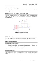
Page 12: ...emote start stop function or interlock control Figure 4 ON OFF input internal layout Connect the 24 VDC power supply to the HV power supply See Table 3 for requirements HV output voltage can be controlled by 1 Internal 4 potentiometer Output voltage and current monitoring is possible on 6 1 6 5 6 6 connector pins 1V pro rata 1kV voltage and 100mA HV current 2 Using CAN see CHAPTER 6 CONTROL VIA CA...

Page 13: ...educe voltage drop or increase the DC supply voltage to compensate it for normal operation VDC can be safely increased up to 26V Red LED lights while HV output is switched on Power supply stops HV output if output current exceeds maximal value To restart operation tur off and turn on of VDC is required The restart can be done using CAN command OFF and following ON ...

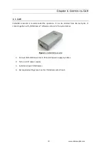
Page 14: ... ordered from Eksma Optics It comes together with CAN Browser software and a set of required cables Figure 5 CAN USB converter 1 Connect CAN USB converter to PC and HV power supply by cables 2 Turn on 24V power supply 3 Install and open CAN Browser 4 Set required settings see CHAPTER 7 CAN BROWSER SETTINGS ...

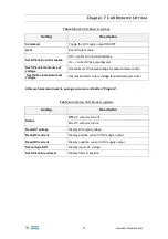
Page 15: ...ntiometer control Set HV knob maximum set voltage Set maximum HV output voltage for potentiometer control After each command need to push green cursor and button Program Table 6 Advanced CAN Browser registers Setting Description Status Off HV output is turn off On HV output is turn on Read HV voltage Display HV output voltage Read HV current Display positive current of HV supply output Read HV cur...

Reviews: