8
www.eksmaoptics.com
Chapter 5
Q
UICK
S
TART
G
UIDE
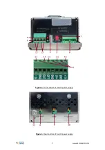
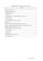
Provide the proper ground connection to ground screw (
#11
) of HV power supply or grounding
by mounting holes.
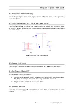
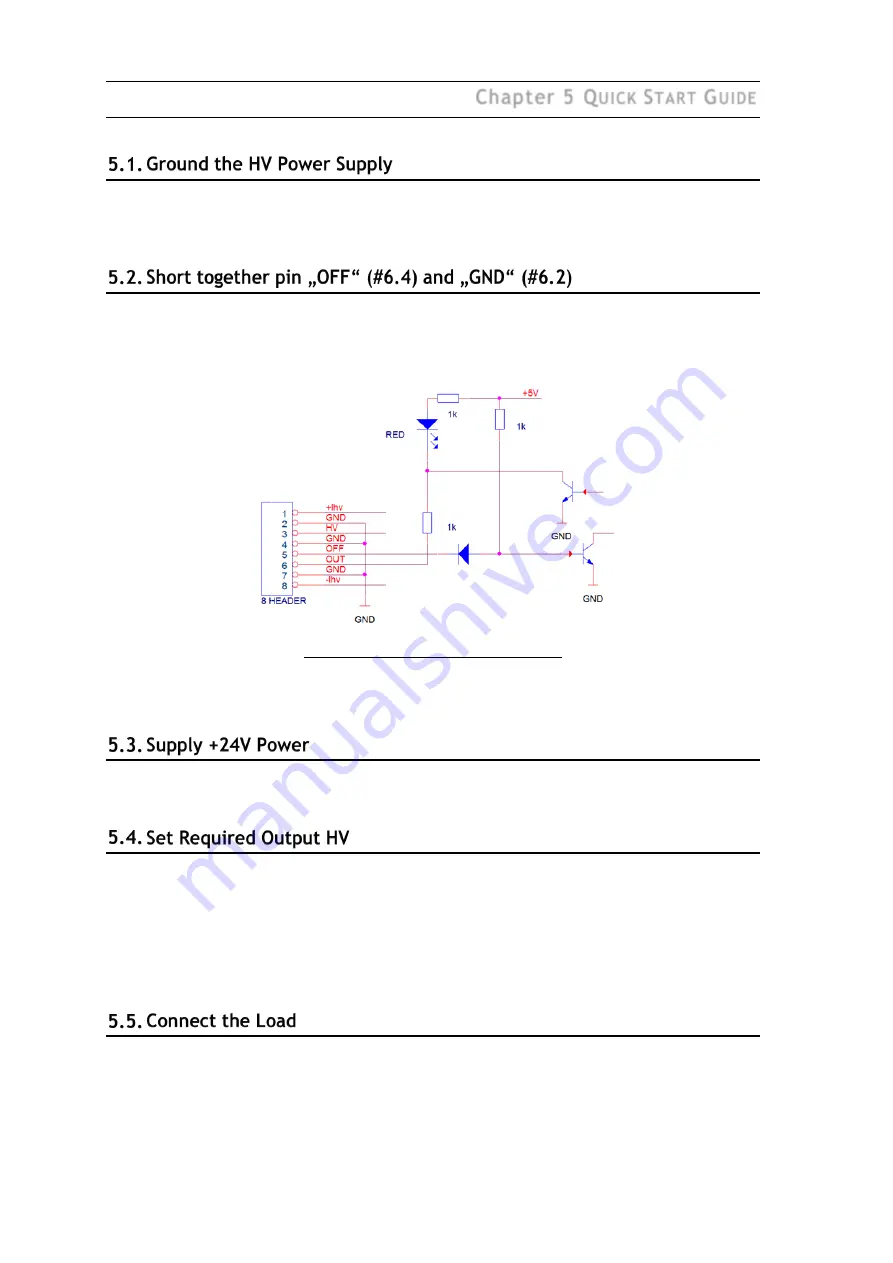
Connection is to enable HV output. This function has priority against CAN command “Power
switch-On”. The input while connected to dry contact, can be used as remote start/stop function
or interlock control.
Figure 4.
ON/OFF input internal layout
Connect the +24 VDC power supply to the HV power supply. See
Table 3
for requirements.
HV output voltage can be controlled by:
1.
Internal
(#4
) potentiometer. Output voltage and current monitoring is possible on (#6.1,
#6.5, #6.6) connector pins. 1V pro rata 1kV voltage and 100mA HV current.
2.
Using CAN, see C
HAPTER
6
C
ONTROL VIA
CAN for details.
Switch the DC power supply off. Connect the load. Check if the connection cables are firmly
attached.


