background image

7. Specifications

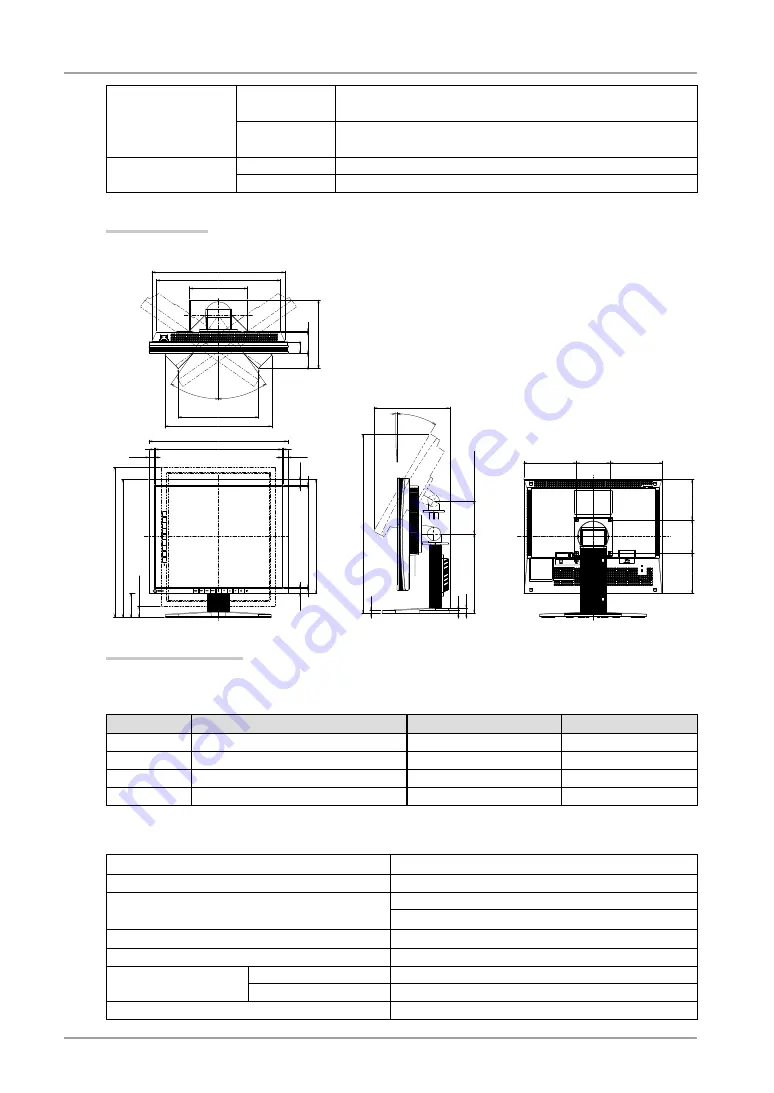
Dimensions

With stand

414mm (W) x 409.5~ 509.5 mm (H) x 204.6 mm (D) 
(16.3”(W) x 16.1” ~ 20.1” (H) x 8.1”(D))

Without stand

414mm (W) x 340mm (H) x 64mm (D)
(16.3”(W) x 13.4”(H) x 2.52”(D))

Weight

With stand

Approx. 7.2 kg (15.9 lbs.)

Without stand

Approx. 5.3 kg (11.7 lbs.)

Dimensions

unit :mm (inches)

303(11.9)

3(0.12)

3(0.12)

340(13.4)

69.5(2.74)

409.5~509.5(16.1~20.1)

414(16.3)

3(0.12)

378.5(14.9)

3(0.12)

35(1.38)

64(2.52)

3(0.12)

47.5(1.87)

35°

35°

SWIVEL

32.5(1.28) (Clockwise)

18.5(0.73)

18.5(0.73)

17.9(0.7)

17.9(0.7)

446.5~546.5(17.6~21.5)(

Clockwise

239(9.4)

370(14.6)

396(15.6)

396(15.6)

157(6.2)

100(3.9)

157(6.2)

120(4.7)

100(3.9)

120(4.7)

172(6.8)

319.2(12.6)

204.6(8.1)

252(9.9)

100(3.9)(Lifting range)

239.5(9.4)

8(0.31)

540.5(21.3)

9.5(0.37)

15(0.59)

30°

1°

TILT


Default Settings

CAL Switch Mode : The default display mode setting is 1-DICOM  mode.

Brightness

Color Temperature

Gamma

1-DICOM

170cd/m

2


7500K

DICOM setting

2-Custom

approx. 200cd/m

2


7500K

2.2

3-CAL

170cd/m

2


7500K

DICOM setting

4-Text

approx. 100cd/m

2


7500K

2.2

Others

Input Priority

1

Smoothing

3

PowerManager

VESA DPMS (Analog input)
DVI DMPM (Digital input)

Screen Size

Normal

Off Timer

Disable

Menu Settings

Menu Position

Center

Menu Off Timer

45 seconds

Language

English

Summary of Contents for RadiForce S110

Page 1: ...uch aufmerksam durch um sich mit der sicheren und effizienten Bedienung vertraut zu machen Bewahren Sie dieses Handbuch zum spateren Nachschlagen auf Important Veuillez lire attentivement ce Manuel d...

Page 2: ...radio communications However there is no guarantee that interference will not occur in a particular installation If this equipment does cause harmful interference to radio or television reception whic...

Page 3: ...It shall be assured that the final system is in compliance to IEC60601 1 1 requirements Instructions for Use User s Manual English...

Page 4: ...rt of this manual may be reproduced stored in a retrieval system or transmitted in any form or by any means electronic mechanical or otherwise without the prior written permission of EIZO Corporation...

Page 5: ...How to use the ScreenManager 18 3 2 ScreenManager menu 19 3 3 Screen Adjustment Analog Input 20 3 4 Color Adjustment 23 3 5 Mode Preset Function Setup Mode Preset 26 3 6 Power Saving Function PowerMa...

Page 6: ...se read this section and the caution statements on the unit refer to the figure below Location of the Caution Statements Symbols on the unit Symbol Location This symbol indicates Rear Main Power Switc...

Page 7: ...ble place A unit placed on an inadequate surface may fall and result in injury or equipment damage If the unit falls disconnect the power immediately and ask your dealer for advice Do not continue usi...

Page 8: ...o not connect or disconnect the power cord in the presence of patients Never touch the plug and power cord if it begins to thunder Touching them may result in electric shock When attaching an arm stan...

Page 9: ...ck the ventilation slots on the cabinet Do not place any objects on the ventilation slots Do not install the unit in a closed space Do not use the unit laid down or upside down Blocking the ventilatio...

Page 10: ...an afterimage may appear Use the screen saver or timer to avoid displaying the same image for extended periods of time Periodic cleaning is recommended to keep the monitor looking new and to prolong i...

Page 11: ...net or panel Tips The optional ScreenCleaner is recommended for cleaning the cabinet and panel surface If necessary the stains on the cabinet and panel surface can be removed by moistening part of a s...

Page 12: ...e monitor is included refer to the EIZO LCD Utility Disk The utility software ScreenManager Pro for Medical for Windows to control the monitor from a PC with mouse keyboard is included refer to the EI...

Page 13: ...Up Right Chooses an adjustment item or increases decreases adjusted values for advanced adjustments using the ScreenManager menu p 18 6 Power Button Turns the power on or off 7 Power indicator 2 Indic...

Page 14: ...t signal connector D Sub mini 15 pin Connector SIGNAL1 11 Input signal connector DVI I Connector SIGNAL2 12 USB port Up Connects the USB cable in order to use the provided software 13 USB port Down Co...

Page 15: ...e are set just by plugging your display into the computer without any manual settings Analog Input Resolution Mode Frequency Dot Clock 640 x 480 VGA 60 Hz 135 MHz Max 640 x 480 VESA 85 Hz 720 x 400 VG...

Page 16: ...h the attached screw in fasteners Analog Input Connect to SIGNAL1 D Sub 15 pin Connector Signal Cable Connector on PC PC Signal cable MD C87 optional Video Output Connector D Sub mini 15 pin Standard...

Page 17: ...tand and easy rotation between the portrait and landscape positions 4 Connect the other end of the power cord to a power outlet WARNING Use the enclosed power cord and connect to the standard power ou...

Page 18: ...mage correctly based on its pre setting data When finished turn off the PC and the monitor Tips Adjust the brightness of the screen depending on the brightness of your environment Be sure to take adeq...

Page 19: ...etting Performance 1 Input from Signal 1 The input signal from Signal 1 is displayed in the following cases When the monitor is turned on When the PC for the Signal 1 is turned on while displaying the...

Page 20: ...tton The sub menu appears 2 Use the Control Buttons to select the desired setting icon and press the Enter Button The setting menu appears 3 Use the Control Buttons to make all required adjustments an...

Page 21: ...olor 1 Brightness 3 4 Color Adjustment p 23 Temperature Gamma Saturation Hue Gain 6 Colors Reset PowerManager DVI DMPM 3 6 Power Saving Function PowerManager p 26 VESA DPMS Others Screen Size 3 11 Dis...

Page 22: ...s Adjustment Procedure About how to use the ScreenManager refer to p 18 1 Press the Auto Adjustment Button on the control panel The message Your setting will be lost if you press again now appears and...

Page 23: ...adjustment Select the Phase and eliminate the horizontal flickering blurring or bars by using the Right and Left Buttons NOTE Horizontal bars may not completely disappear from the screen depending on...

Page 24: ...st the horizontal resolution using the Right and Left Buttons 3 Adjust the output signal range Dynamic Range of the signal Use the Range Adjustment p 42 of Screen menu This controls the level of outpu...

Page 25: ...electing the CAL Switch mode Press the Mode Button while the CAL Switch menu is displayed Pressing Mode Button allows you to select the following mode 1 DICOM 2 Custom 3 CAL 4 Text 1 DICOM Making colo...

Page 26: ...turation Hue Gain 6 colors Reset 1 These settings can also be adjusted on the CAL Switch menu p 23 2 When calibration is performed in this mode using the calibration kit RadiCS LE see Optional p 39 on...

Page 27: ...tion To change the saturation 100 100 Selecting the minimum level 100 makes the image monochrome NOTE The Saturation adjustment may cause undisplayable color tone Hue Sets the hue value for flesh tone...

Page 28: ...t to conserve energy turn off the monitor when you finished using it Disconnecting the monitor from the power supply is recommended to save energy completely Even if the monitor is in a power saving m...

Page 29: ...hout use How to set 1 Select Off Timer in the ScreenManager Others menu 2 Select Enable and press the Right and Left Buttons to adjust the On Period 1 to 23 hours Off timer system PC Monitor Power Ind...

Page 30: ...s power on To unlock 1 Switch off the monitor s power by the Power Button on the control panel 2 Hold down the Auto Adjustment Button once again and turn the power back on NOTE The adjustment lock fu...

Page 31: ...hers menu 2 Select the screen size with the Up and Down Buttons Menu Explanation Full Screen Stretches the image to cover the full screen regardless of the image s resolution Since the vertical resolu...

Page 32: ...oothing setting may not be required depending on the display resolution You cannot choose the smoothing icon Adjusting the brightness of the black area surrounding the displayed image Procedure 1 Sele...

Page 33: ...t Using the USB Rev 2 0 compatible PC or peripherals is recommended If the monitor is in the power saving mode or if the monitor is connected to the power outlet with the monitor turned off all the de...

Page 34: ...or Windows ScreenManager Pro for Medical for Windows or ToneCurve Tuning Utility Refer to the corresponding User s Manual on the CD ROM disk in order to install and use the software When using the abo...

Page 35: ...h it to meet the following tilt angles of the monitor Up 45 degrees down 45 degrees horizontal display and vertical display rotated 90 degrees clockwise Connect the cables after attaching an arm or a...

Page 36: ...ssing the Power Button 2 The message below appears These messages appear when the signal is not inputted correctly even if the monitor functions properly The message appears when the signal is not inp...

Page 37: ...CD product 7 Interference patterns or pressure marks remain on the screen Leave the monitor with a white or black screen The symptom may disappear 8 Noise appears on the screen When entering the signa...

Page 38: ...28 18 The Auto Adjustment Button does not operate The Auto Adjustment Button does not operate when the digital signal is input Make sure that the adjustment lock is off p 28 This function does not wor...

Page 39: ...al input without USB load Main power off 0W Input Connector D sub mini 15pin DVI I Analog Input Signal Sync Separate TTL Positive Negative Composite TTL Positive Negative Sync on Green 0 3 Vp p Negati...

Page 40: ...546 5 17 6 21 5 Clockwise 239 9 4 370 14 6 396 15 6 396 15 6 157 6 2 100 3 9 157 6 2 120 4 7 100 3 9 120 4 7 172 6 8 319 2 12 6 204 6 8 1 252 9 9 100 3 9 Lifting range 239 5 9 4 8 0 31 540 5 21 3 9 5...

Page 41: ...2 1 or later Network QC Management Software EIZO RadiNET Pro Ver 3 2 1 or later Cleaning Kit EIZO ScreenCleaner For the latest information about the accessories and information about the latest compat...

Page 42: ...ata0 C3 Analog Blue 8 Analog Vertical Sync 18 T M D S Data0 C4 Analog Horizontal Sync 9 T M D S Data1 19 T M D S Data0 5 Shield C5 Analog Ground analog R G B return 10 T M D S Data1 20 NC NC No Connec...

Page 43: ...gnal input only The other is DVI I connector for both digital and analog signal inputs DVI DMPM DVI Digital Monitor Power Management The Power management system for the digital interface The Monitor O...

Page 44: ...eratures the white tone appears somewhat Green while at lower temperatures it appears somewhat red Computer monitors generally give best performance at high temperature settings 5000 K Slightly reddis...

Page 45: ...stment menu HINWEIS Je nach angeschlossenem PC kann die Anzeigeposition variieren sodass Justierungen mithilfe des Justierungsmen s erforderlich sein k nnen Wird ein Eingangssignal verwendet das in de...

Page 46: ...Hz Posi Posi 48 08 72 19 VESA 800 600 75Hz 49 5 MHz Posi Posi 46 88 75 00 VESA 800 600 85Hz 56 3 MHz Posi Posi 53 67 85 06 VESA 1024 768 60Hz 65 0 MHz Nega Nega 48 36 60 00 VESA 1024 768 70Hz 75 0 MHz...

Page 47: ...peration in the configuration in which it will be used Guidance and manufacturer s declaration electromagnetic emissions The RadiForce series is intended for use in the electromagnetic environment spe...

Page 48: ...line s to earth 1kV line s to line s 2kV line s to earth Mains power quality should be that of a typical commercial or hospital environment Voltage dips short interruptions and voltage variations on...

Page 49: ...as determined by an electromagnetic site surveya should be less than the compliance level in each frequency rangeb Interference may occur in the vicinity of equipment marked with the following symbol...

Page 50: ...y of transmitter m 150kHz to 80MHz d 1 2 P 80MHz to 800MHz d 1 2 P 800MHz to 2 5GHz d 2 3 P 0 01 0 12 0 12 0 23 0 1 0 38 0 38 0 73 1 1 2 1 2 2 3 10 3 8 3 8 7 3 100 12 12 23 For transmitters rated at a...

Page 51: ...Befestigung des Standfusses mu derart erfolgen da die oberste Zeile der Bildschirmanzeige nicht h her als die Augenh he eines Benutzers in sitzender Position ist c Im Fall eines stehenden Benutzers mu...

Page 52: ...ion All rights reserved http www eizo com http www eizo co jp 924 8566 153 153 Shimokashiwano Hakusan Ishikawa 924 8566 Japan Phone 81 76 277 6792 Fax 81 76 277 6793 8 5B Phone 86 512 6252 0100 Fax 86...

Reviews: