background image

E

53

2       USING THE SCREENMANAGER

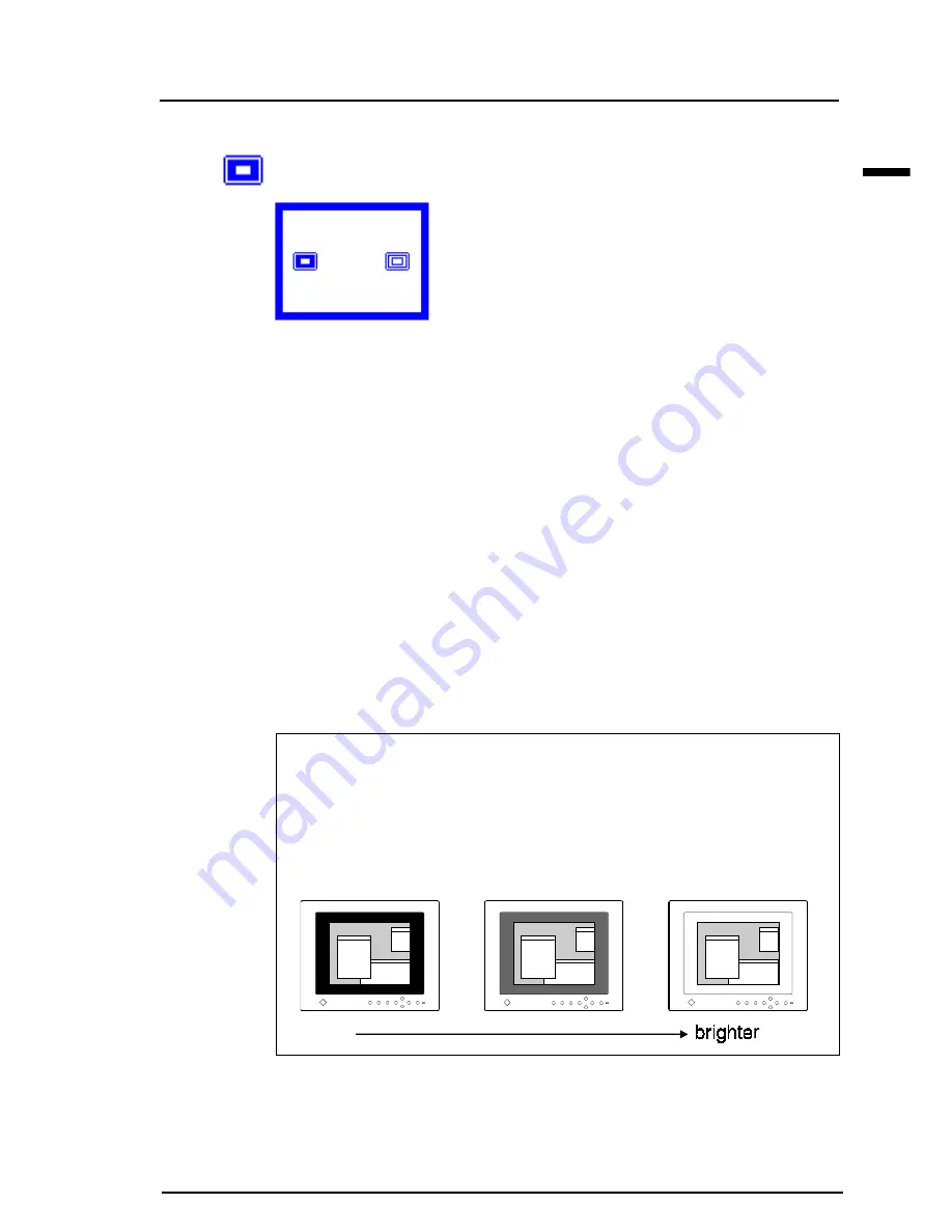
Border Intensity

This function is used for changing the brightness of the black area sur-
rounding the displayed image.

Adjustment Procedure

Please adjust the border intensity using the following procedure:

(1)Select the “Border Intensity” icon and push the Enter button to display

the adjustment menu.

(2)Adjust the brightness of the border area using the right and left buttons.

(3)Push the Enter button to return to the “Others” menu.

(4)Select the “Return” icon and push the Enter button to return to the

main menu of the ScreenManager.

(5)Select the “Exit” icon and push the Enter button to exit the

ScreenManager.

What is the "Border Intensity" function?

With lower resolutions of (640 x 480, 800 x 600, etc.) the image is
displayed at the center of the screen and the outer area (border) is
usually black.  The “Border Intensity” function can set the brightness of
this border area to any brightness level that maybe desired.

Summary of Contents for FlexScan L360

Page 1: ...E...

Page 2: ...7 2 1 How to use the ScreenManager 27 About ScreenManager 27 ScreenManager Menus 27 How to use the ScreenManager 30 Adjustment Lock 31 2 2 Screen Adjustment 32 About Screen Adjustments 32 Adjustment P...

Page 3: ...on confidential unless prior arrangements are made pursuant to EIZO NANAO CORPORATION s receipt of said information Although every effort has been made to ensure that this manual provides up to date i...

Page 4: ...ou autres objets Be careful as this unit may be hot Do not place this unit on carpets or cover with cloth etc Vorsicht Das Ger t ist m glicherweise hei Ger t keinesfalls auf Teppichb den stellen und...

Page 5: ...t all power connections immediately and contact your dealer for advice Attempting to use a malfunctioning LCD monitor can be dangerous Do not dismantle the cabinet or modify the LCD monitor Dismantlin...

Page 6: ...P Parallel blade Grounding type 125 V 10 A In Europe Rating min 250 V 10 A Length max 2 1 m Type H05VV F 3G 1 mm2 Use a plug type approved by the country where you use Failure to do so may cause fire...

Page 7: ...g injury or breaking the monitor free mount type LCD monitor must be securely attached to the appropriate mount using the bracket and the screw enclosed To attach the mount to the LCD please read the...

Page 8: ...ualified service engineer before using it again Using a LCD monitor after it has been dropped may result in fire or electric shock Disconnect the power cord and or the power unit when moving the LCD m...

Page 9: ...ay have some defective pixels These pixels may appear as slightly light or dark areas on the screen This is due to the characteristics of the panel itself and not the LCD product The backlight of the...

Page 10: ...type and the free mount type Please note that there are some points which vary according to the type Package Contents Desktop Stand Type If any of the above listed items are missing or damaged please...

Page 11: ...ler for assistance We recommend that you retain the original packing materials in case of future need LCD Monitor Signal Cable MD C91 Power Unit Bracket 6 of 4 mm x 10 mm 2 of 4 mm x 30 mm mounting sc...

Page 12: ...ns up down right and left buttons and the Enter button are used to enter adjustments and settings when using the ScreenManager menu 6 Power Button This button switches the monitor s power ON and OFF o...

Page 13: ...ini 15 pin Input Connectors Input Signal 1 and 2 5 Maintenance Port Service use only 6 USB Ports Upstream Port x 1 Downstream Ports x 4 See page 60 for further details 7 Security Lock Allows for conne...

Page 14: ...trol Buttons The four control buttons up down right and left buttons and the Enter button are used to enter adjustments and settings when using the ScreenManager menu 6 Power Button This button switch...

Page 15: ...rvice use only 5 Security Lock Allows for connection of a security cable This lock supports the Kensington s MicroSaver security system For further information please consult below Kensington 2855 Cam...

Page 16: ...ow fH 30 kHz 61 kHz fV 50 Hz 85 Hz The maximum resolution of this LCD monitor is 1024 x 768 at a maximum fV of 75 Hz Using the LCD monitor with Windows 95 98 A Monitor information file is saved in the...

Page 17: ...3 Plug the signal cable which is marked LCD into the D Sub connector Signal 1 at the rear of the monitor Please ensure that the arrow mark on the casing of the connector is visible when connecting Se...

Page 18: ...nal cable 6 Replacing the connector cover and the rear cover a To close easily the LCD monitor should be tilted forward as shown in the diagram When tilting the panel take care not to catch your finge...

Page 19: ...n the rear of the LCD monitor Plug the other end into a power outlet 8 Turn on the monitor s main power and then switch on the PC power 9 This completes the installation Turn off the main power when y...

Page 20: ...NSTALLATION 1 To open easily the LCD monitor should be tilted forward as shown in the diagram 2 Pull the rear cover clear while pushing the push buttons on the top 3 Pull down and remove the connector...

Page 21: ...dealers for information about optional cables Be sure that the monitor and the PC are both switched off before connecting them Be sure to connect the cable securely Selecting the Active Input The Inp...

Page 22: ...e OFF Lay the LCD monitor as shown below 2 Plug the power unit into the power connector in the rear of the LCD monitor 3 Remove the D Sub connector holder a Hand loosen the screws at the center of the...

Page 23: ...necting See note When connecting the signal cable check that the shape of the cable connector matches the shape on the LCD monitor 5 Replace the D Sub connector holder and hand tighten the screw 6 a P...

Page 24: ...n that position where it is manually moved The arm stand shall have the ability to be tilted the monitor forward and backward The height of the upper row should be 500 mm or less in the lowest positio...

Page 25: ...al free mount type monitors please be sure to observe the followings Do not pile the power units Set the power units at minimum intervals of 20 mm Refer to the diagram below 9 Turn on the monitor s ma...

Page 26: ...MD C91 only or with Macintosh adapter when connecting the second computer to the monitor Contact EIZO dealers for information about optional cables Be sure that the monitor and the PC are both switch...

Page 27: ...ScreenManager consists of a main menu and six sub menus Screen Color PowerManager Others Information and Language Animated icons on each menu allows for easy adjustment Main menu The menu message for...

Page 28: ...4 pg 36 PowerManager menu Use this menu to configure the power saving features Default setting is VESA setting Ch 5 pg 39 Others menu Use this menu to configure the following features Screen Size Col...

Page 29: ...r each page is as follows Page 1 Screen menu settings Page 2 Color adjustment settings Page 3 PowerManager settings Page 4 Others menu settings Language menu Use this menu to select the ScreenManager...

Page 30: ...desired setting icon and push the Enter button 3 The setting menu appears Use the Control buttons to make all required adjustments Save To save settings and go back to the previous menu push the Enter...

Page 31: ...ration can be disabled by holding down the Auto adjustment button while switching on the LCD monitor s power This will disable lock the Enter button and Auto adjustment button protecting from accident...

Page 32: ...s have been preset in theL360 monitor s memory and require no screen adjustment If the mode input to the LCD monitor is not one of the preset modes the adjustments must be made using the Auto adjustme...

Page 33: ...hat the monitor be tilted to eye level To make adjustment easily install and run the Screen Adjustment Program in the attached utility disk Before adjustment read the readme txt file Do not continuous...

Page 34: ...on on the front panel The following message will appear and remain on the screen for 5 seconds While the message is on the screen push the button again to automatically adjust the screen position If y...

Page 35: ...look at the illustration and the explanation below i If the screen is free from any bars of distortion proceed to step 6 Position adjustment ii If horizontal flickering or horizontal bars appear proc...

Page 36: ...stment a Select the Position icon and push the Enter button to enter the Position menu Adjustment markers are displayed on each corner of the screen b Adjust the position of the upper left corner of t...

Page 37: ...h the Enter button to show the Contrast Brightness menu b Press the Auto adjustment button on the front panel while displaying the Contrast Brightness menu to automatically adjust contrast c The scree...

Page 38: ...is section gives more detailed information on various features Please follow the previously explained adjustment procedure for screen adjust ment 1 Clock Adjustment This feature decreases the vertical...

Page 39: ...rols the screen position The number of screen pixels and the screen position are fixed for the LCD monitor Only one position is right and the displayed image should be adjusted to this position 4 Reso...

Page 40: ...lution is increased When pushing the down or left buttons the resolution is decreased The maximum resolution for the EIZO L360 LCD monitor is 1024 x 768 5 Contrast Adjustment This feature controls the...

Page 41: ...contrast adjustment is required except when the graphics board or the resolution is changed from the previous one 6 Brightness Adjustment This feature controls the brightness of the screen The brightn...

Page 42: ...You can select from these color tones when using white background applications with Windows or Macintosh Note that the 3 color modes are similar when using black background applications Mode 1 default...

Page 43: ...or 3 and push the Enter button You will hear a long beep indicating the option is selected 3 Gain Adjustment Gain The Gain adjustment has no effect on the starting point the black level It changes on...

Page 44: ...image Reset You can recall the default color gain setting for the current color mode 1 2 3 using the Reset icon The values shown in percentages represent the current level within the specific adjustme...

Page 45: ...saving mode it will return to a normal display immediately when the mouse or keyboard is operated The EIZO PowerManager functions comply with the VESA DPMS standard and the EPA s Energy Star guideline...

Page 46: ...tem works with a screen saver software and Energy Saver for Macintosh which blanks the screen totally black screen Set the monitor to match the PC s power saving software as follows Monitor setting fo...

Page 47: ...ing into a power saving mode VESA DPMS Power Saving Method VESA DPMS utilizes four signals ON STANDBY SUSPEND and OFF The monitor detects these signals from the graphics board and executes power savin...

Page 48: ...the monitor enters power saving mode EIZO MPMS Power Saving Method When the PC is entering a ScreenSaver Energy Saver mode it interacts to the monitor and the monitor shifts to a power saving mode aft...

Page 49: ...s energy consumption of the monitor What is ENENRGY STAR ENERGY STAR is a set of power saving guidelines issued by the U S Environmental Protection Agency EPA The guidelines apply to PC systems and pe...

Page 50: ...al size or enlarged to fit the full screen of the LCD panel Setup Procedure Please setup the screen size using the following procedure 1 Select the Screen Size icon and push the Enter button to show t...

Page 51: ...se display modes of 680 x 480 720 x 400 800 x 600 can be enlarged to full screen When selecting the Enlarged mode the image is enlarged to almost the full screen size When selecting the Normal mode th...

Page 52: ...turn to the main menu of the ScreenManager 4 Select the Exit icon and push the Enter button to exit the ScreenManager The default setting is On true color 16 million What is the Color Enhancer functio...

Page 53: ...area using the right and left buttons 3 Push the Enter button to return to the Others menu 4 Select the Return icon and push the Enter button to return to the main menu of the ScreenManager 5 Select...

Page 54: ...being present at either input the monitor automatically detects and displays that signal Priority setting Performance If signals from both inputs are present the monitor gives preference to Signal 1...

Page 55: ...thers menu 4 Select the Return icon and push the Enter button to return to the main menu of the ScreenManager 5 Select the Exit icon and push the Enter button to exit the ScreenManager Off Timer The O...

Page 56: ...page 57 To Delay Entering Power Off To delay entering the Power Off mode press the power button on the front panel located to the left of the LED light during the advance notice period The monitor wi...

Page 57: ...nnected correctly PC turned off Monitor received unsupported signal frequency Two short beeps Monitor is in the advance notice mode of the Off every Timer The power will be off within fifteen fifteen...

Page 58: ...ter button to return to the Others menu 4 Select the Return icon and press Enter to return to the main menu of the ScreenManager 5 Select the Exit icon and push the Enter button to exit the ScreenMana...

Page 59: ...r button to show the adjust ment menu 2 Select Reset using the up and down buttons A confirmation message will appear 3 Push the Enter button to proceed and return to the Others menu 4 Select the Retu...

Page 60: ...s about this feature When the monitor is not on the peripherals connected to the downstream ports will not operate When the monitor is in a power saving mode the connected USB compliant devices will o...

Page 61: ...inish to complete the installation Once the above operation is completed the monitor functions as a USB hub and the USB compliant peripherals can be connected to the downstream ports of the monitor Fo...

Page 62: ...SB For details refer to the manual of the PC Check that the USB cable is correctly connected Check the downstream ports by connecting the peripherals to other downstream ports If the problem is solved...

Page 63: ...erly connected to the graphics board or PC Check that the graphics board is correctly inserted in the PC Switch the signal input by pushing the input signal selection button on the front control panel...

Page 64: ...ht be damaged Please contact the dealer The monitor may be located close to a device that is generating a magnetic field Such devices include speakers electric motors high voltage cables and other mon...

Page 65: ...the screen becomes dark or begins to flicker please contact your dealer When the screen image has been changed after displaying the same image for a long period after images may appear Use the Off Tim...

Page 66: ...adjustment function is intended for use on Macintosh and IBM compatibles PCs running Windows It may not work properly if either of the following applies You are running an AT compatible PC on MS DOS...

Page 67: ...lation within the monitor may result in fire or equipment failure Please keep the monitor in a dust free environment Never use thinner benzene alcohol ethanol methanol or isopropyl alcohol abrasive cl...

Page 68: ...cer function in the Others menu Recommended Resolution 1024 dots x 768 lines Input Signal Sync H V Separate TTL Positive Negative H V Composite TTL Positive Negative Sync on Green 0 3 Vp p Negative Vi...

Page 69: ...Color Enhancer function in the Others menu Recommended Resolution 1024 dots x 768 lines Input Signal Sync H V Separate TTL Positive Negative H V Composite TTL Positive Negative Sync on Green 0 3 Vp p...

Page 70: ...i...

Page 71: ...pin 2 Green video 10 Ground 3 Blue video 11 shorted 4 Ground 12 Data 5 No pin 13 H Sync 6 Red ground 14 V Sync 7 Green ground 15 Clock 8 Blue ground Shell Ground USB ports Desktop Stand Type Only Upst...

Page 72: ...nregistr s en usine dans le microprocesseur du moniteur conform ment au diagramme de synchronisation ci dessous A Front Porch Vordere Schwarzschulter Front avant B Sync Period Synchronimpuls D lai de...

Page 73: ...800 x 600 36 0 MHz 35 16 kHz 56 25 Hz 0 667 24 0 028 1 2 000 72 0 057 2 VESA 800 x 600 40 0 MHz 37 88 kHz 60 32 Hz 1 000 40 0 026 1 3 200 128 0 106 4 VESA 800 x 600 50 0 MHz 48 08 kHz 72 19 Hz 1 120 5...

Page 74: ...09 3 556 128 0 626 22 6 222 224 0 711 25 22 222 17 067 28 444 17 778 800 600 1024 625 2 200 88 0 5607 23 6 400 256 0 739 28 20 000 15 840 26 400 16 579 800 600 1056 628 1 280 64 0 478 23 4 800 240 1 3...

Page 75: ...es FRONT VIEW VORDERANSICHT VUE DE FACE SIDE VIEW SEITENANSICHT VUE DE COTE TOP VIEW DRAUFSICHT VUE D EN HAUT 397 15 6 4 5 5 1 7 15 6 397 4 0 4 1 5 18 3 45 5 1 7 4 5 9 1 9 37 5 1 4 9 3 3 28 8 2 3 2 17...

Page 76: ...SIDE VIEW SEITENANSICHT VUE DE COTE TOP VIEW DRAUFSICHT VUE D EN HAUT Free Mount Type LCD Monitor mm inches FRONT VIEW VORDERANSICHT VUE DE FACE 397 15 6 45 5 1 7 4 5 9 1 9 37 5 1 4 8 2 3 2 3 12 4 17...

Page 77: ...uters The labelling scheme was developed as a joint effort by the TCO The Swedish Confederation of Professional Employees Svenska Naturskyddsforeningen The Swedish Society for Nature Conservation and...

Page 78: ...layers of certain computer displays Cadmium damages the nervous system and is toxic in high doses The relevant TCO 99 requirement states that batteries the colour generating layers of display screens...

Page 79: ...1995 EN50082 1 1992 EN61000 3 2 1995 EN61000 3 3 1995 Hinweis zur Ergonomie Dieser Monitor erf llt die Anforderungen an die Ergonomie nach ZH1 618 10 80 durch die Ansteuerung mit der VGA Videokarte 10...

Page 80: ...995 EN61000 3 3 1995 Hinweis zur Ergonomie Dieser Monitor erf llt die Anforderungen an die Ergonomie nach ZH1 618 10 80 GS VW SG7 01 97 mit dem Videosignal 1024 Punkte x 768 Zeilen RGB analog 0 7Vp p...

Page 81: ...ommunications However there is no guarantee that interference will not occur in a particular installation If this equipment does cause harmful interference to radio or television reception which can b...

Reviews: