background image

40

SETTING

This function turns Projection Lamp off when this projector detects
signal interruption and is not used for a certain period in order to
reduce power consumption and maintain Lamp-life.  (This projector is
shipped with this function ON.)

Power Management function operates to turn Projection Lamp off
when input signal is interrupted and any button is not pressed over 5
minutes.  This function operates as follows;

1. When any input signal is interrupted, “No signal” and counting

down display appears (for 5 minutes).

2. After counting down for 5 minutes, projector lamp and READY

indicator are turned off.

3. When READY indicator flashing, Projection Lamp can be

turned on again (Power Management mode).  
In this Power Management mode, Projection Lamp is
automatically turned on when input signal connected or
projector is operated with any button on Side Control or on
Remote Control Unit again.
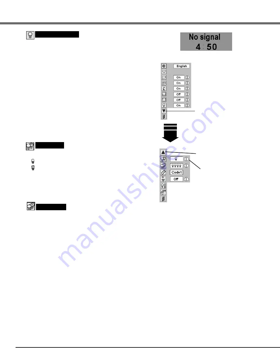
Power management

Time left until Lamp off.

Press SELECT button at this icon to
display other items.

Lamp Mode

NOTE :

After changing Lamp Mode, it cannot be switched again for 90 seconds.

This Projector is equipped with 4 Projection Lamps and a number of using lamps can be switched to 4 lamps or 2 lamps.
Using 2 lamps maintain life of Projection Lamps.  

To change over Lamp Mode

1.  Press MENU button and ON-SCREEN MENU will appear.  Press POINT LEFT/RIGHT buttons to select SETTING and

press SELECT button.  Setting dialog box appears.

2. Press POINT DOWN button to move a red frame pointer to “Lamp mode”.  Set "4 lamps mode" or "2 lamps mode" by

pressing POINT LEFT/RIGHT button(s).  When Lamp Mode is set from "4 lamps mode" to "2 lamps mode" image
becomes little darker.  When Lamp Mode is set from "2 lamps mode" to "4 lamps mode" image become brighter
gradually.

Press SELECT button at this icon to
display previous items.

Move a pointer to item and then
press POINT LEFT/RIGHT
button(s).

This function allows you to change brightness of the screen.

····

normal brightness.

····

lower brightness reduces the lamp power consumption

and extends the lamp life.

Lamp control

Summary of Contents for LC-XT9

Page 1: ...Projection lens is optional MULTIMEDIA PROJECTOR MODEL LC XT9 OWNER S INSTRUCTION MANUAL...

Page 2: ...pace on the top sides and rear of the projector cabinet for allowing air circulation and cooling the projector Minimum clearances must be maintained If the projector is to be built into a compartment...

Page 3: ...he projector This projector should be operated only from the type of power source indicated on the marking label If you are not sure of the type of power supplied consult your authorized dealer or loc...

Page 4: ...with the limits for a Class A digital device pursuant to Part 15 of FCC Rules These limits are designed to provide reasonable protection against harmful interference when the equipment is operated in...

Page 5: ...SOURCE 34 SELECTING VIDEO SYSTEM 35 PICTURE IMAGE ADJUSTMENT 36 IMAGE LEVEL SELECT 36 IMAGE LEVEL ADJUSTMENT 37 PICTURE SCREEN ADJUSTMENT 38 SETTING MENU 39 MAINTENANCE 42 WARNING TEMP INDICATOR 42 AI...

Page 6: ...r Management function is provided to reduce power consumption while a projector is not in use This Power Management function operates to turn Projection Lamp off when a projector detects signal interr...

Page 7: ...s operating power of Cooling Fans FRONT OF CABINET LAMP COVER ADJUSTABLE FEET This projector is equipped with cooling fans for protection from overheating Pay attention to following to ensure proper v...

Page 8: ...ct a projector with peripheral equipment before turning a projector on Refer to pages 13 16 for connection CONNECTING AC POWER CORD Connect AC Power Cord supplied to a projector AC outlet must be near...

Page 9: ...NS SHIFT ADJUSTMENT MOVED UP OR DOWN MOVED LEFT OR RIGHT Use LENS SHIFT button and POINT UP DOWN button to move image up or down Refer to page 24 Use LENS SHIFT button and POINT LEFT RIGHT button to m...

Page 10: ...ected on proper position Adjust height of rear adjustable feet by rotating them until projector properly stabled on table Press knob and retract handle REAR ADJUSTABLE FEET Refer to P7 INSTALLING PROJ...

Page 11: ...by 2 or more people To retract carrying handles pull up lock buttons and release lock of handles and press handles fully in until it s locked Pull up lock buttons to release lock PREPARATION CAUTION I...

Page 12: ...it Plug into Socket 3 4 ANALOG RGB R Pr G Y B Pb H HV V CONTROL PORT DVI INPUT 1 R C JACK USB RESET MONO MONO MONO MONO CONTROL PORT AUDIO CONTROL PORT INPUT 2 INPUT 3 INPUT 4 AUDIO AUDIO SERIAL PORT...

Page 13: ...JACKS 5 BNC INPUT JACKS Connect component video output Cr Y Cb or Pr Y Pb from video equipment to R Pr G Y and B Pb jacks or connect computer output 5 BNC Type Red Green Blue Horiz Sync and Vert Sync...

Page 14: ...AUDIO OUT R L R L R R L L SERIAL PORT OUT TERMINAL SERIAL PORT IN TERMINAL This port is used to service this projector Connect USB port of computer to this port If you control a projector by computer...

Page 15: ...esktop type Laptop type Audio Cable stereo Audio Output Audio Input AUDIO OUT Cables used for connection Cables are not supplied with this projector VGA Cable HDB 15 pin DVI Cable BNC Cable BNC x 5 Au...

Page 16: ...BNC x 3 DVI Cable HDB 15 pin Scart 21 pin Cable DVI VGA Adapter Audio Cable RCA x 2 Cables are not supplied with this projector NOTE When connecting cable power cords of both a projector and external...

Page 17: ...adjust value in MENU It is also used to pan image in DIGITAL ZOOM mode P33 Used to execute item selected It is also used to expand image in DIGITAL ZOOM mode P33 Used to turn a projector on or off P2...

Page 18: ...a projector is turned on And bright when a projector is in stand by mode P50 INDICATORS WARNING TEMP INDICATOR This indicator flashes red when internal projector temperature is too high P42 50 WARNING...

Page 19: ...de P33 Used to execute item selected It is also used to expand compress image in DIGITAL ZOOM mode P33 Used to adjust zoom P24 ZOOM BUTTONS FOCUS BUTTON Used to adjust focus P24 NO SHOW BUTTON Used to...

Page 20: ...eries Danger of explosion if battery is incorrectly replaced Dispose of used batteries according to batteries manufacturers instructions and local rules Pull up lid and remove it Remove battery compar...

Page 21: ...to operate each adjustment on ON SCREEN MENU 2 MOVING POINTER 3 SELECT ITEM Move pointer see below or adjust value of item by pressing POINT button s on Side Control or on Remote Control Unit Select...

Page 22: ...rast Brightness Color Tint Color Temp White balance R G B Sharpness Gamma Noise Reduction Progressive Refer to P37 38 FOR VIDEO SOURCE Press MENU BUTTON while connecting to VIDEO input source Same fun...

Page 23: ...off Projection Lamp automatically Refer to Power Management on pages 39 and 40 Press POWER ON OFF button again to turn off projector LAMP indicator lights bright and READY indicator turns off After a...

Page 24: ...disappears after 4 seconds Zoom Focus ZOOM ADJUSTMENT FOCUS ADJUSTMENT 1 Press ZOOM button on Side Control or on Remote Control Unit Message Zoom is displayed 2 Press ZOOM button to make image larger...

Page 25: ...e Control Unit to black out a image To restore to normal press NO SHOW button again or press any other button except POINT UP DOWN LEFT RIGHT and SELECT button NO SHOW FUNCTION Message disappears afte...

Page 26: ...to INPUT source that you want to select and then press SELECT button 1 2 INPUT 1 2 button INPUT 1 INPUT 2 Move a pointer red arrow to source and press SELECT button Move a pointer red arrow to Input 1...

Page 27: ...plays system being selected Systems on this dialog box can be selected Press MENU button and ON SCREEN MENU will appear Press POINT LEFT RIGHT buttons to move a red frame pointer to PC SYSTEM Menu ico...

Page 28: ...a red frame pointer to AUTO PC Adj icon and press SELECT button PC ADJUST MENU Auto PC Adj PC ADJUST Menu icon Store adjustment parameters Adjustment parameters from Auto PC Adjustment can be memoriz...

Page 29: ...er to PC ADJUST Menu icon 1 2 Press POINT DOWN button to move a red frame pointer to item that you want to adjust and then press SELECT button Adjustment dialog box will appear Press POINT LEFT RIGHT...

Page 30: ...t a screen Full screen Reset Store Closes PC ADJUST MENU Quit Other icons operates as follows 3 To store adjustment parameters move a red frame pointer to Store icon and then press SELECT button Move...

Page 31: ...Normal picture level preset on this projector Standard Picture level with improved halftone for graphics Real User preset picture adjustment in IMAGE ADJUST Menu P32 IMAGE 1 4 IMAGE SELECT Menu icon I...

Page 32: ...here you want to set and then press SELECT button Store icon Press SELECT button at this icon to store adjustment IMAGE ADJUST Menu icon Press POINT LEFT button to lighten red tone and POINT RIGHT but...

Page 33: ...20p HDTV 1035i HDTV 1080i 50 HDTV or 1080i 60 HDTV is selected on PC SYSTEM Menu P27 True and Digital Zoom cannot be operated when 480i 575i 480p or 575p is selected on PC SYSTEM Menu P27 This project...

Page 34: ...tton Source Select Menu Press POINT DOWN button to move a red arrow pointer to Input 2 and then press SELECT button Source Select Menu will appear 2 SELECTING INPUT SOURCE MENU OPERATION DIRECT OPERAT...

Page 35: ...detects incoming Video signal and adjusts itself to optimize its performance When Video System is 1035i 1080i50 or 1080i60 select system manually first If projector cannot reproduce proper video imag...

Page 36: ...l picture level preset on this projector Standard Picture level adjusted for picture with fine tone Cinema User preset picture adjustment in IMAGE ADJUST Menu P38 IMAGE 1 4 IMAGE SELECT Menu icon IMAG...

Page 37: ...n proper color From 0 to 63 Color Tint Press POINT LEFT button to soften image and POINT RIGHT button to sharpen image From 0 to 15 Sharpness Press POINT LEFT button to lighten red tone and POINT RIGH...

Page 38: ...or 1080i 60 is selected on AV SYSTEM Menu P35 Move a red frame to function and press SELECT button SCREEN MENU SCREEN Menu icon Provides image at a wide screen ratio of 16 9 Wide Provides image at a...

Page 39: ...g English German French Italian Spanish Portuguese Dutch Swedish Russian Chinese Korean and Japanese Display This function decides whether to display On Screen Displays On shows all On Screen Displays...

Page 40: ...me left until Lamp off Press SELECT button at this icon to display other items Lamp Mode NOTE After changing Lamp Mode it cannot be switched again for 90 seconds This Projector is equipped with 4 Proj...

Page 41: ...h to Use position in the compartment lid on back of the remote control And then while holding down the MENU button press the IMAGE button number of times corresponding to the remote control code for t...

Page 42: ...on WARNING TEMP READY LAMP REPLACE LAMP REAR INDICATORS Air filters help prevent dust from accumulating on the optical elements inside the projector To whatever extent the air filters become clogged w...

Page 43: ...l replace lamp LAMP REPLACE indicator lights yellow LAMP REPLACE indicator flashes yellow Projection lamp is defective or fails to be turned on Restart a projector on and make sure lamp is on If this...

Page 44: ...lay Figure shows case of replacing LAMP 2 LAMP 1 LAMP 2 LAMP 3 LAMP 4 CAUTION DO NOT OPERATE A PROJECTOR WHILE ANY OF LAMPS IS REMOVED IT MAY RESULT IN MALFUNCTIONS FIRE HAZARD OR OTHER ACCIDENTS NOTE...

Page 45: ...MENU will appear Press POINT LEFT RIGHT button s to move a red frame pointer to SETTING Menu icon 1 Press POINT DOWN button to move a red frame pointer to Lamp counter reset and then press SELECT butt...

Page 46: ...ervice station for a checkup of the unit and replacement of the lamp Additionally check carefully to ensure that there are no broken shards or pieces of glass around the projector or coming out from t...

Page 47: ...may be turned on by pressing Power ON OFF button Check WARNING TEMP and READY indicator If both WARNING TEMP and READY indicator flashes a projector cannot be turned on See TURNING ON OFF PROJECTOR se...

Page 48: ...0 31 On Off 0 63 0 63 Input RGB Analog RGB Scart Go to System 1 Input 2 Y Pb Cb Pr Cr Computer Input Input 3 Input 1 PC Adjust 640 x 480 720 x 400 800 x 600 1024 x 768 1152 x 864 1280 x 1024 1400 x 1...

Page 49: ...age 4 Screen Setting English German French Italian Spanish Portuguese Dutch Swedish Chinese Korean Japanese On Off On Off On Off On Off On Off On Off On Off 4 Lamp 2 Lamp Code 1 Yes No Keystone Blue b...

Page 50: ...being cooled down It cannot be turned on until the READY indicator lights green Projector Condition The projector is operating normally The projector is cooled down enough and the temperature returns...

Page 51: ...ace 61 20 65 20 71 40 75 60 50 00 86 00 50 00 94 00 XGA 1 1024 x 768 XGA 2 1024 x 768 XGA 3 1024 x 768 XGA 4 1024 x 768 48 36 60 00 68 677 84 997 XGA 6 1024 x 768 60 023 75 03 XGA 7 1024 x 768 56 476...

Page 52: ...0 00 ON SCREEN DISPLAY RESOLUTION H Freq kHz V Freq Hz D WXGA 1 1366 x 768 48 36 60 00 D WXGA 4 1360 x 768 56 16 72 00 D 1035i 1920 x 1035 Interlace 33 75 60 00 D 1080i 60 1920 x 1080 Interlace 33 75...

Page 53: ...tteries Remote Control Transmitter 480i 480p 575i 575p 720p 1035i 1080i 50 and 1080i 60 High Definition TV Signal AC 120 V 12 A Max Ampere 50 60 Hz The U S A and Canada AC 200 240 V 7 5 A Max Ampere 5...

Page 54: ...signal Connect display output terminal of computer to this terminal with DVI cable not supplied 1 9 17 2 10 18 3 11 19 4 12 20 5 13 21 6 14 22 7 15 23 8 16 24 C1 C2 C3 C5 C4 T M D S Data2 No Connect...

Page 55: ...Depth 0 315 8 0 9 90 251 5 10 15 258 0 5 18 131 5 9 90 251 5 5 7 2 36 60 0 30 83 783 0 17 56 446 0 22 87 581 0 9 25 235 0 8 62 219 0 17 56 446 0 7 01 178 0 7 01 178 0 4 23 107 5 3 26 82 8 9 72 247 0...

Page 56: ...6126 9371 14 E Mail info eiki de Eastern Europe EIKI CZECH spol s r o Umeleck 15 170 00 Praha 7 Czech Republic Tel 42 02 20570024 42 02 20571413 Fax 42 02 20571411 E Mail easterneurope eiki de Japan W...

Page 57: ...he surface And be careful not to hold or subject the lens to strong forces It may damage the lens cabinet or mechanical parts For details of the lens and installation contact the sales dealer where yo...

Page 58: ...following procedure below 1 Remove Lens Cover Remove 2 Screws A Push part B and pull Upper Lens Cover up See Fig 1 2 Remove 4 Screws C Pull Lower Lens Cover toward front and remove See Fig 2 3 Remove...

Page 59: ...screws attached on lens Connect the Lens Motor Lead connector to the socket on the right top of the lens attachment Motor Driven Lens only See Fig 5 Fig 6 Fig 7 LENS LOCK RELEASE LENS LOCK 5 Grasp the...

Page 60: ...d BACK on Light Block Sheets are correct and set them properly Light Block Sheets For each lens Fig 8 LIGHT BLOCK SHEETS Make sure the sheet figures are correct and put in proper position LIGHT BLOCK...

Page 61: ...r Lens Cover and set them in front of the flap See Fig 9 Fix Lower Lens Cover with 4 Screws C See Fig 2 9 Replace Upper Lens Cover Slide Light Block Sheets into the guide of Upper Lens Cover and set t...

Page 62: ...ns is 1 meter set mark yellow of the lens on Focus Lock Screw position 3 Lock the Focus Lock Screw securely When proper focus is not observed at outer area of the screen proceed following adjustments...

Page 63: ...s insert the accessory in between the lens attachment and the lens to correct the focus Correcting the focus Spacer 1 Color Clear Thickness 0 1 mm 60 inch projection Screen Inserting the spacers corre...

Page 64: ...21 6 16 0 18 9 14 6 13 1 10 1 43 3 31 1 31 5 24 4 25 2 18 7 21 6 16 7 15 0 11 5 49 5 35 5 36 0 27 9 28 8 21 4 27 1 20 9 18 7 14 4 61 8 44 3 45 0 34 8 36 1 26 8 32 6 25 1 22 5 17 3 74 2 53 1 54 0 41 8...

Reviews: