background image

15

Installation

Installation

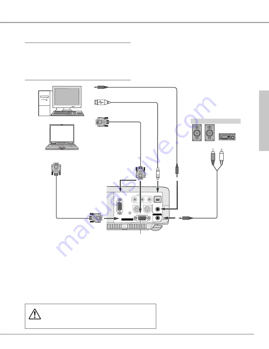
Connecting to a Computer

COMPUTER  IN  

1

DVI - I

MONITOR  OUT

S-VIDEO

COMPUTER IN 

2 / 

COMPONENT IN 

COMPUTER

 / 

COMPONENT

AUDIO  IN

AUDIO  IN

R

VIDEO

L

USB

SERVICE PORT 

RESET

(MONO)

ARIALE)

AUD

COMPUTER  IN  

1

MONITOR  OUT

S-VIDEO


COMPUTER


/ COMPONENT

AUDIO  IN

AUDIO  IN

R

VIDEO

L

USB

SERVICE PORT 

RESET

(MONO)

/ COMPONENT  IN  

COMPUTER  IN  2

/   

AUDIO  OUT

(VARIABLE)

Cables used for connection

• VGA Cables (Mini D-sub 15 pin) (Only one cable is supplied.)
• USB Cable 

• Audio Cables (Mini Plug: stereo) 

(

= Not supplied with this projector.)

External Audio Equipment

VGA cable 

USB cable 

Audio cable (stereo) 

Audio cable 

(stereo)

Monitor Output

USB port

Audio Output

COMPUTER IN 1/ COMPONENT IN
(or COMPUTER IN 2/ MONITOR OUT)

USB

COMPUTER/ COMPONENT
AUDIO IN

AUDIO OUT
(stereo)

Audio Input

This terminal is switchable. Set up the
terminal as either Computer input or
Monitor output.  (See Page 41.)

VGA cable 

Monitor Input

COMPUTER IN 2/ MONITOR OUT

Note:

When connecting the cable, the power cords of both the projector
and the external equipment should be disconnected from AC
outlet. 

Note:

• If you wish to use PAGE 

ed

buttons on the remote control, connect USB

port of your computer to the USB socket of the projector.  (p9 and 42)

• When connecting AUDIO OUT to external audio equipment, the projector's

built-in speaker is disconnected.

• When the cable is of the longer variety, it is advisable to use the

COMPUTER IN 1 / COMPONENT IN and not the COMPUTER IN 2 /
MONITOR OUT. 

• Input sound to the COMPUTER/COMPONENT AUDIO IN terminal when

using the COMPUTER IN 2/ MONITOR OUT terminal as input.

Summary of Contents for LC-XB28

Page 1: ...MULTIMEDIA PROJECTOR OWNER S MANUAL MODEL LC XB28...

Page 2: ...H mm 4 3 aspect ratio Zoom min Zoom max 40 813 x 610 4 9 1 5m 3 3 1 0m 3 3 1 0m Inch Diagonal Center 1AA6P3P1186 KD6B 100 2032 x 1524 12 8 3 9m 8 2 2 5m 150 3048 x 2286 19 3 5 9m 12 5 3 8m 195 3962 x...

Page 3: ...Zoom Bildgr e B x H mm Bildseitenverh ltnis 4 3 Zoom min Zoom max 40 813 x 610 1 5m 1 0m 1 0m Zoll Diagonale Mitte 1AA6P3P1188 KD6B D 100 2032 x 1524 3 9m 2 5m 150 3048 x 2286 5 9m 3 8m 195 3962 x 29...

Page 4: ...male Taille d cran L x H mm Taux d aspect 4 3 Zoom min Zoom max 40 813 x 610 1 5m 1 0m 1 0m Pouces en diagonale Centre 1AA6P3P1189 KD6B F 100 2032 x 1524 3 9m 2 5m 150 3048 x 2286 5 9m 3 8m 195 3962 x...

Page 5: ...pporto larghezza altezza 4 3 Zoom min Zoom max 40 813 x 610 1 5m 1 0m 1 0m Diagonale pollici Centro 1AA6P3P1190 KD6B I 100 2032 x 1524 3 9m 2 5m 150 3048 x 2286 5 9m 3 8m 195 3962 x 2972 7 7m 5 0m 300...

Page 6: ...de la pantalla An x Al mm Relaci n de pantalla 4 3 Zoom m n Zoom max 40 813 x 610 1 5m 1 0m 1 0m Pulgadas en diagonal Centro 1AA6P3P1191 KD6B E 100 2032 x 1524 3 9m 2 5m 150 3048 x 2286 5 9m 3 8m 195...

Page 7: ...for the starting display of the projector with the Capture function You can also display the captured image in an interval during your presentation instead of blackout the image with the No show funct...

Page 8: ...ment 23 Computer Input 24 Input Source Selection 24 Computer System Selection 25 Auto PC Adjustment 26 Manual PC Adjustment 27 Image Level Selection 29 Image Level Adjustment 30 Screen Size Adjustment...

Page 9: ...maintained Do not cover the ventilation slot on the projector Heat build up can reduce the service life of your projector and can also be dangerous If the projector is not to be used for an extended...

Page 10: ...tage points or short out parts that could result in a fire or electric shock Never spill liquid of any kind on the projector Do not install the projector near the ventilation duct of air conditioning...

Page 11: ...mp life and cause a fire hazard Openings in the cabinet are provided for ventilation and to ensure reliable operation of the product and to protect it from overheating and these openings must not be b...

Page 12: ...ult the dealer or an experienced radio TV technician for help Use of shielded cable is required to comply with class B limits in Subpart B of Part 15 of FCC Rules Do not make any changes or modificati...

Page 13: ...for attaching u Air Intake Vent 6 Exhaust Vent 6 i 5 2 4 3 o 1 0 CAUTION Hot air is exhausted from the exhaust vent Do not put heat sensitive objects near this side q w e r t y u Back Front 2 Lamp Cov...

Page 14: ...IO IN Connect the audio output from video equipment connected to r or i to this jack When the audio output is monaural connect it to L MONO jack p16 y AUDIO IN COMPUTER COMPONENT Connect the audio out...

Page 15: ...9 t POWER indicator Blink red until the projector gets ready to be turned on It turns red when the projector is in the stand by mode It remains green while the projector is under operation p52 w INPUT...

Page 16: ...use these buttons 0 y D ZOOM ed buttons Select the Digital zoom mode and resize the image p31 u AUTO PC button Automatically adjust a computer image to its optimum setting p26 i IMAGE button Select an...

Page 17: ...to moisture or heat Do not drop the remote control If the battery has leaked on the remote control carefully wipe case clean and install new batteries Risk of explosion if battery is replaced by an i...

Page 18: ...9 1 Screen Size W x H mm 4 3 aspect ratio Zoom min 40 Zoom max 813 x 610 5 2 1 6m 4 3 1 3m 100 2032 x 1524 13 1 4 0m 10 8 3 3m 150 3048 x 2286 20 0 6 1m 16 4 5 0m 200 4064 x 3048 26 6 8 1m 22 0 6 7m 3...

Page 19: ...projector is not in use When this projector is connected to an outlet with the AC power cord it is in Stand by mode and consumes a little electric power Connecting the AC Power Cord Connect the AC pow...

Page 20: ...r COMPUTER IN 2 MONITOR OUT USB COMPUTER COMPONENT AUDIO IN AUDIO OUT stereo Audio Input This terminal is switchable Set up the terminal as either Computer input or Monitor output See Page 41 VGA cabl...

Page 21: ...Plug stereo Not supplied with this projector Note When connecting the cable the power cords of both the projector and the external equipment should be disconnected from AC outlet Note The S VIDEO jac...

Page 22: ...A Cable Component VGA Cable Component Cable Not supplied with this projector Note When connecting the cable the power cords of both the projector and the external equipment should be disconnected from...

Page 23: ...ojector with your PIN code Pointer After the OK icon disappears you can operate the projector PIN code Input Dialog Box Turning On the Projector Basic Operation Enter a PIN code Select a number by pre...

Page 24: ...down enough to be turned on again the POWER indicator will become red Then you can disconnect the AC power cord The message will disappear after 4 seconds Note The projector cannot be turned on durin...

Page 25: ...ns Remote Control How to Operate the On Screen Menu MENU button SELECT button POINT button outer ring On Screen Menu Quit Exit this menu The projector can be adjusted or set via the On Screen Menu Ref...

Page 26: ...image Contrast Brightness Color Tint Color temp White balance R G B Sharpness Gamma Progressive Film p36 37 For video source Same function as computer menu Input Menu Used to select input source eith...

Page 27: ...Reduce the upper width with Point e button Reduce the lower width with Point d button 1 Press the KEYSTONE button on the top control the remote control or select Keystone in the Setting Menu p39 The k...

Page 28: ...the sound To restore sound to its previous level press the MUTE button again or press the VOLUME buttons Press the Point 8 button to turn up the volume and press the Point 7 button to turn down the vo...

Page 29: ...ource is analog coming from a computer through the COMPUTER IN 1 COMPONENT IN terminal select RGB RGB INPUT button Input Source Selection Direct Operation Menu Operation Computer Input Move the pointe...

Page 30: ...lected as a signal source this projector automatically detects the signal format and tunes to project a proper image without any additional setting Signal formats provided in this projector is shown o...

Page 31: ...Adjustment function When the image is not provided properly with this operation manual adjustments are required p27 28 The Auto PC Adjustment cannot be operated when 480i 575i 480p 575p 720p 1035i or...

Page 32: ...ointer to an item and press the SELECT button PC Adjust Menu PC Adjust Menu icon Eliminate the flicker from the image displayed Press the Point 7 8 buttons to adjust value From 0 to 31 Fine sync Adjus...

Page 33: ...5 in which you want to store and then press the SELECT button To reset the adjusted data select Reset and press the SELECT button The confirmation box will appear and then select Yes All adjustments...

Page 34: ...Real Blackboard Green Image 1 Image 2 Image 3 and Image 4 by pressing the IMAGE button on the remote control IMAGE button Standard Real Blackboard Green Image 1 Image 2 Image 3 Normal picture level p...

Page 35: ...utton to lighten red tone and the Point 8 button to deepen red tone From 0 to 63 White balance Red Press the Point 7 button to lighten green tone and the Point 8 button to deepen green tone From 0 to...

Page 36: ...s modified to fit the screen size in initial mode The panning function may not operate properly if the computer system prepared in the PC Adjust Menu is used The minimum compression ratio can be limit...

Page 37: ...matically detects incoming video signal and adjusts itself to optimize its performance The projector selects connection in the following order 1st S Video 2ndVideo The S VIDEO jack has priority over t...

Page 38: ...nt connected to the COMPUTER IN 1 COMPONENT IN terminal with a Component VGA Cable select Component Component When the input source is coming from video equipment connected to the COMPUTER IN 1 COMPON...

Page 39: ...3 PAL M PAL N The projector automatically detects incoming video signal and adjusts itself to optimize its performance If the projector cannot reproduce proper video image it is necessary to select a...

Page 40: ...rol Normal picture level preset on this projector Standard Picture level adjusted for the picture with fine tone Cinema Blackboard Green User preset image in the Image Level Adjustment Menu p36 37 Ima...

Page 41: ...is icon to display other items Image Adjust Menu icon Press the Point 7 button to lighten color and the Point 8 button to deepen color From 0 to 63 Press the Point 7 8 buttons to obtain proper color F...

Page 42: ...eo source With this function on the projector reproduces pictures faithful to the original film quality Film Note Progressive cannot be selected when 480p 575p 720p 1035i or 1080i is selected in the A...

Page 43: ...ess the Point d button and move the red frame pointer to the function that you want to select and then press the SELECT button 1 2 Move the red frame to a function and press the SELECT button Screen M...

Page 44: ...is not detected When pressing the SELECT button at Language the Language Menu appears Setting Menu Language Setting Menu icon This function corrects distortion of a projected image Select either Store...

Page 45: ...s function decides the start up display as follows User the image you captured Default the factory set logo Off count down only Enter a Logo PIN code Select a number by pressing the Point 7 8 buttons...

Page 46: ...oled down the power will be turned off Off Power management function is off Then set the countdown timer with the Point 7 8 buttons Setting Ceiling Rear Ceiling When this function is On the picture is...

Page 47: ...ock If the top control accidentally becomes locked and you do not have the remote control nearby disconnect the AC power cord from the AC outlet and then while pressing the SELECT button reinsert the...

Page 48: ...tomatically move to Set Press the SELECT button so that you can change the following PIN code lock settings If you entered an incorrect PIN code PIN code and the number will turn red and disappear Ent...

Page 49: ...amp counter to the factory default settings Select Factory default and this box appears Select Yes and the next box appears Factory default Select Yes to activate it This function provides you the fol...

Page 50: ...provide appropriate space for the projector to be ventilated Check the installing condition to see if ventilation slots are not blocked Is the projector not installed near the ventilation duct of air...

Page 51: ...ulate on the LCD panel and the projection mirror degrading picture quality Do not put small parts into the air intake vents It may result in malfunction of the projector RECOMMENDATION We recommend av...

Page 52: ...e amount of cleaner Abrasive cleaners solvents or other harsh chemicals might scratch the surface 2 Follow these steps to clean the projector cabinet When the projector is not in use put the projector...

Page 53: ...45 minutes Loosen 2 screws of the lamp with a screwdriver and pull out the lamp by grasping the handle 1 3 Replace the lamp with a new one and tighten the 2 screws back into position Make sure that t...

Page 54: ...eplace the lamp with a new one IMMEDIATELY after the projector has cooled down Follow carefully the instructions in the Lamp Replacement section of this manual Continuous use of the lamp with the LAMP...

Page 55: ...e between the projector and the projection screen See page 13 Check the projection lens to see if it needs cleaning See page 47 Moving the projector from a cool to a warm place may result in moisture...

Page 56: ...e set See pages 18 and 43 Computer 2 cannot be selected Select Computer 2 at the Terminal item in the Setting Menu See page 41 The Terminal item cannot be selected The Terminal item in the Setting Men...

Page 57: ...e POWER indicator lights red and the projector can be turned on The WARNING indicator keeps blinking Check and clean the air filters Projector Condition The projector is ready to be turned on with the...

Page 58: ...1 Computer Input Video Auto Go to System 3 Go to System 3 Computer 1 Video S Video PC Adjust 640 x 480 720 x 400 800 x 600 1024 x 768 1152 x 864 1280 x 1024 1400 x 1050 Mode 1 Mode 2 Mode 3 Mode 4 Mo...

Page 59: ...lian Spanish Portuguese Dutch Swedish Chinese Korean Japanese Store Reset On Off On Off Off On Off On Off Off On Off Normal Code 1 Yes No Keystone Blue back Display Logo Ceiling Rear Power management...

Page 60: ...lace 63 34 59 98 SXGA 5 1280 x 1024 SXGA 6 1280 x 1024 SXGA 7 1280 x 1024 63 74 60 01 71 69 67 19 SXGA 10 1280 x 960 81 13 76 107 60 00 60 00 XGA 1 1024 x 768 XGA 4 1024 x 768 48 36 60 00 XGA 6 1024 x...

Page 61: ...Projection Lamp 200W Interface Video Input Jacks RCA Type x 1 Video and Mini DIN 4 pin x 1 S Video Audio Input Jacks RCA Type x 2 Computer Input1 Component Input Terminal VGA HDB15 Terminal X 1 Compu...

Page 62: ...ver with String and Screw PIN Code Label The specifications are subject to change without notice LCD panels are manufactured to the highest possible standards Even though 99 99 of the pixels are effec...

Page 63: ...reen Ground Blue 1 5 2 4 3 6 7 8 Horiz sync Input Output Composite H V sync Ground Vert sync Ground Vert sync Input Output 9 13 10 12 11 14 15 Pin Configuration Vcc Data Data Ground 1 2 3 4 USB CONNEC...

Page 64: ...Memo PIN Code Lock No Logo PIN Code Lock No Factory default set No 1 2 3 4 Factory default set No 4 3 2 1 Should the four digit number be changed the factory set number will be invalid Put a label be...

Page 65: ...schland Tel 06126 9371 0 Fax 06126 9371 14 E Mail info eiki de Eastern Europe EIKI CZECH spol s r o Umeleck 15 170 00 Praha 7 Czech Republic Tel 42 02 20570024 42 02 20571413 Fax 42 02 20571411 E Mail...

Reviews: