Quick Operation Manual for ER210-2700 Industrial Robot
23
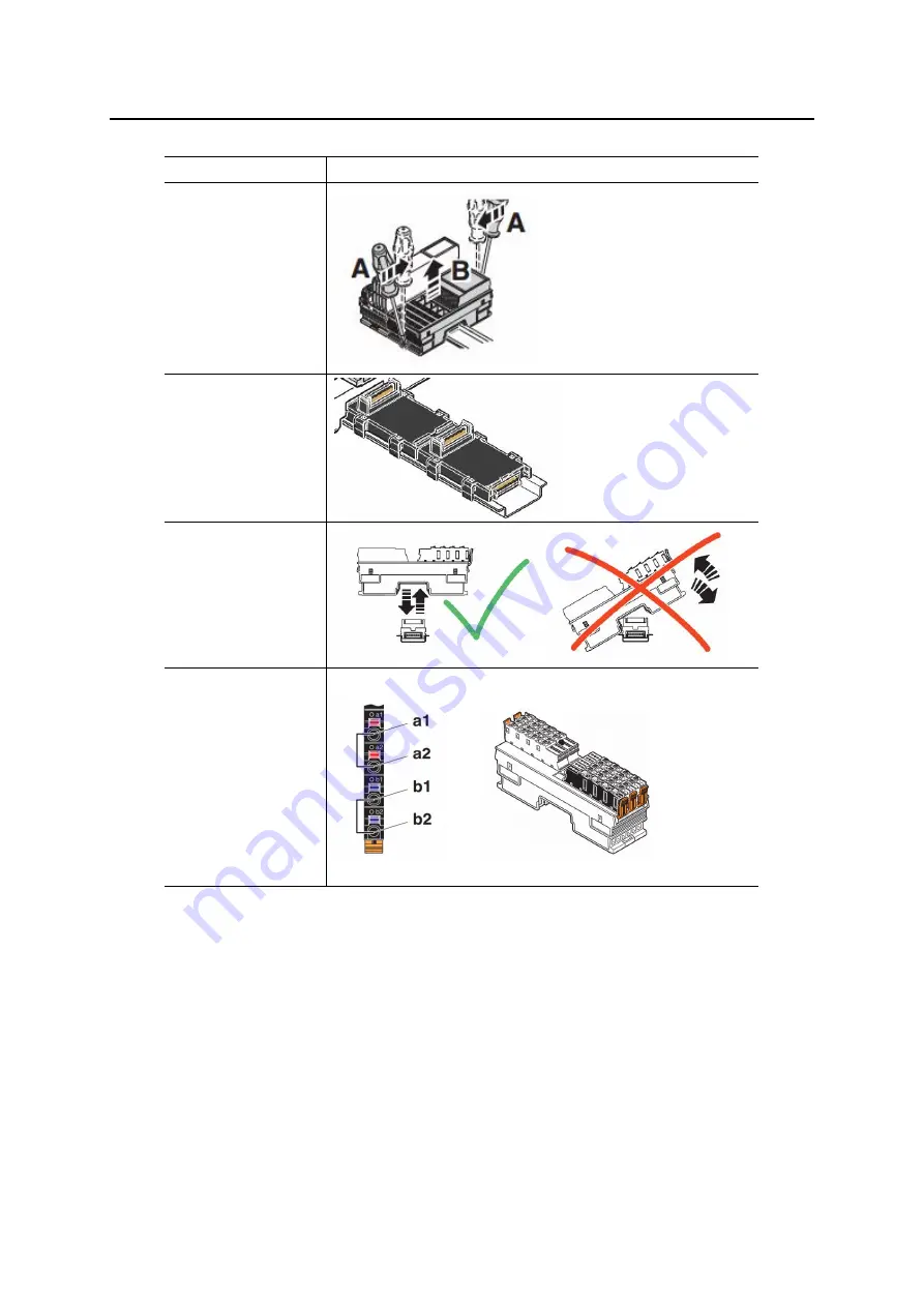
Table 3-7 Procedures for Local IO Expansion
Procedures
Demonstration
1.Remove
the
controller from the
DIN rail.
2. Connect the bus
coupler and the
bus basic module.
Mount
the
combination on the
DIN trail.
3.Mount
the
controller on the
bus coupler and
mount the I/O
module on the bus
basic module.
4. Connect the
a1/a2 pins of I/O
module to the 24
voltage
positive
source and connect
the b1/b2 pins of
I/O to the 24
voltage
negative
source.
3.4.2 Remote IO Module Expansion
The remote IO module expansion complies with the EtherCAT bus communication protocols. The
RJ45 type interfaces can be directly connected through an Ethernet cable without being limited by the inner
space of the control cabinet.
Table 3-8 Remote IO Module Expansion
Summary of Contents for ER210-2700
Page 6: ......


