background image

E D R O  

D

y n a

W

a s h

®

  T

h r e e

  P

o c k e T

  W

a s h e r

  -   e

x T r a c T o r s

110

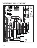
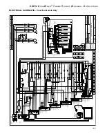
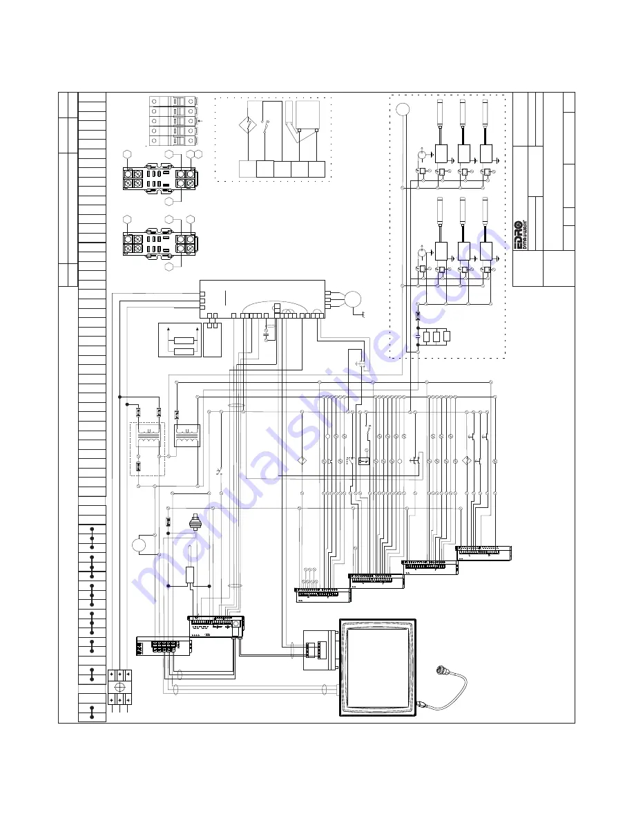
ELECTRICAL SCHEMATIC - 

DW Hard Mount & Soft Mount with VFD

5(9

'(6&5,37,21

'$

7(

(&2

-81

':

(3':765

(3':76

':

92/

76

5HPRYHG2Q2I

I6ZLWFK

2&7

7

0$,13:5

0$,13:5

)

)

$

$

/

/

/$

/$

3

%

9

%

$

)

)

$

$

3/&3:5

'&&20

)

$

2=21(

127(

)86( )86(

$

#9

$&

$

#9

$&

&XWOHU+DPPHU

(/&36

3:5

6833/

<

<

<

<

<

<

<

;

<

<

&

;

;

;

;

;

;

/9

32:(5

V V

;

(/&(;11'5

(/&

,1

2

8

7

&2/':

$7(5

<

'2253

,1

<

'5$,1

<

2=21(

<

%8==(5

<

+27

:

$7(5

<

127

8

6('

9

$&

&20021

2

3803

;

3:5&

(//

;

3:5&

(//

;

3:5&

(//

;

'2256

:,7&+

;

9'&

&20021

2

3803

;

3:5&

(//

;

3:5&

(//

;

6723

56

56

;

;

(/&3$$$'5

<

<

<

&

<

VV

;

;

;

;

;

;

9

'$

581

&+

&20

,

&+

,

9

$'

32:(5

(5525

%$

7

/2:

581581

%$

7

/2:

(5525

32:(5

,

9

9

&+

&+

,

$/$50

$

'

3/&

,1

2

8

7

35(666:$'&+9

9)'61

&

:

$6+

5(9

9)'6

<

:

$6+)

:'9

)'

6

<

7(03

352%($'&+9

127

86('

-803(5 9)'9

127

86('

127

86('

127

86('

127

86('

3/&

127

86('

127

86('

9)'29(5/2$'; 9,%5$

7,216:;

9'&&20021

<

<

<

<

<

<

;

<

<

&

;

;

;

;

;

;

/9

32:(5

V V

;

(/&(;11'5

(/&

,1

2

8

7

67($09

$/

9(

<

9

$&

&20021

6833/

<

<

6833/

<

<

6833/

<

<

6833/

<

<

6833/

<

<

6833/

<

<

(

67

23

;

9'&

&20021

527

$7,216

(1625

;

127

8

6('

127

8

6('

127

8

6('

3:5&

(//

;

+,*+6

/,3

%

5$.,1*

<

<

<

<

<

<

<

;

<

<

&

;

;

;

;

;

;

/9

32:(5

V V

;

(/&(;11'5

(/&

,1

2

8

7

9

$&

&20021

6833/

<

<

6833/

<

<

6833/

<

<

6833/

<

<

127

8

6('

,1'(;6

2/

<

;

;

;

;

)520'<12=21(

`

)8

6(

)8

6(

7

)8

6(

9,%5$

7,216

:

;

%

%

(0(5*(1&<

6

723

;

&5

<

<

<

<

<

<

'2253

,1

'5$,1

2=21(

237

%8==(5

&2/':

$7(5

+27

:

$7(5

'225

352;,0,7<

6:,7&+

<

<

<

<

<

6833/

<

6833/

<

6833/

<

6833/

<

6833/

<

6833/

<

<

<

67($0

237

127

8

6('

-2*3

%

;

127

8

6('

127

8

6('

127

8

6('

127

8

6('

127

8

6('

127

8

6('

<

+,*+6

/,3

%

5$.,1*

%

%

%

%

%

%

%

%

3

/$

/$

/

/

/

/

9$5,$%/(

0$

027

25

5

7

7

7

)5(48(1&< '5,9(9)'

61

6

6

0&

6

7

5

6

7

5

6

7

8

9

:

6

&5

6

%

%

&5

3

:

$7(5/

(9(/

6

:

6803

7(03

3

52%(

6803

)

9

$&$

)

9

$&$

)

9

$&$

)8

6(

)

9

$&$

616&

75$16)250(5

7


)86(

21/

<

86('

,1

+,*+

92/

7$*(

&21),*85$

7,216

6((

7$%/(

)25

)86(

6,=,1*

,)

127

5(48,5('

&211(&7

-803(56

%(7:((1

/

$


3

$

1'

%(7:((1

/$


35,0$5

<

&21),*85('

)25

6,7(

35,0$5

<

9

$&

6(&21'$5

<

9

$&

9'&

&20021

)$1

3

(/(&75,&$/

3

$1(/

)

$1

5('

%/.

&/($5

5('

%/.

:+7

<

<

<

6833/

<

6833/

<

6833/

<

6833/

<

<

%5$.,1*5

(6,67

25

':

5('

:+7

25$1*(

%/8( :+,7(

5('

*5((1

25$1*(

%/8

:+7

5('

%/.

'2253

,16

:

;

$,56

(16256

:

;

:56'

5$,1

<

:569

$/

9(

<

/,0,7681/(6627+(5

:,6(63(&,),('

)5$&7,216'(&,0$/6

$1*/(60,187(6685)

$&(6

'2127

6&$/('5$

:,1*6

$33529('%<

5(91

02'(/

),/(

7,7/(

'$

7(

6&$/(

3$5

7180%(5

6+((7

'5$

:1%<

.(%

(/(&75,&$/

6&+(0$

7,&

121(

2)

7KH('52&RUSRUDWLRQ &RPPHUFH6WUHHW

(DVW%HUOLQ&7

86$

5

$87+25,=$

7,21)2586(

7KLVGRFXPHQWLVDXWKRUL]HGIRU XVHDVVSHFLILHGE\WKH('52 &253

'RQRWXVHSUHYLRXV

UHYLVLRQVZLWKRXWDSSURYDO

$XWKRUL]HGE\BBBBBBBBBBBBB

'DWHBBBBBBBBBBBBBBBBBBBBB

35235,(7

$5

<

$1'

&21),'(17,$/

7KHLQIRUPDWLRQFRQWDLQHGLQ

7KLV

GUDZLQJLVWKHVROHSURSHUW\RIWKH ('52&RUSRUDWLRQ

$Q\

UHSURGXFWLRQLQSDUWRUDVDZKROH ZLWKRXWWKHZULWWHQSHUPLVVLRQRIWKH ('52&RUSRUDWLRQLVSURKLELWHG

%

127

86('

(;7(51$/ 86%325

7

/

/

/

527

$5

<

',6&211(&7

6:,7&+

;

527

$7,21

6(1625

%51

%/.

%/8

%

;

%

12

1&

6$)(

',6$%/( ,1387

+

+&

9$5,$%/(

$

$&

5

5

-803(56 5

WR

6

5

WR

6

',3

6ZLWFK

6

LQ

WKH

21

SRVLWLRQ

6

6

*51

&20081,&$

7,21

3/8*

&211(&76

72

&20325

7

02'%86

&20081,&$

7,21

:,7+9)'

<

<

<

<

<

<

;

<

<

&

;

;

;

;

;

;

/9

32:(5

V V

;

(/&(;11'5

(/&

,1

2

8

7

9

$&

&20021 127

8

6('

127

8

6('

127

8

6('

127

8

6('

127

8

6('

127

8

6('

127

8

6('

127

8

6('

,1'(;3

52;<

6

:

;

127

8

6('

,1'(;3

%

;

)25

:

$5'3

%

;

5(9(56(3

%

;

127

8

6('

9'&

&20021

127

8

6('

-2*%

5$.(

<

;

;

;

`

;

)520'<12=21(

$,56

(1625

6:,7&+

;

%

;

23(1

'2253

,1

6:,7&+

&/26('

%51

*51

%

;

%

-2*3

%

%

6

5('

<

<

:569

$/

9(

237

:56'

5$,1

237

<

,1'(;6

2/

237

%

%

,1'(;3

52;,0,7<

6

:,7&+

;

%

;

;

;

%

%

%

,1'(;3

%

)25

:

$5'3

%

5(9(56(3

%

-2*%

5$.(

<

3

%

'<12=21(237,21

5&

1(7:25.6

5&

1(7:25.6

32:(5&(// %$//$67

32:(5&(//

5('3

$,5

%/8(3

$,5

32:(5&(// %$//$67

32:(5&(//

5('3

$,5

%/8(3

$,5

32:(5&(// %$//$67

32:(5&(//

5('3

$,5

%/8(3

$,5

3

)8

6(

5&

1(7:25.6

$

%

%

%

%

;

;

;

;

)

9

$&$

&5

'<12=21(3803

&6:

&6:

&6:

&6:

)$1

'<12=21()

$1

$

$

$

$

32:(5&(// %$//$67

32:(5&(//

5('3

$,5

%/8(3

$,5

32:(5&(// %$//$67

32:(5&(//

5('3

$,5

%/8(3

$,5

32:(5&(// %$//$67

32:(5&(//

5('3

$,5

%/8(3

$,5

%

%

%

%

;

;

;

;

'<12=21(3803

&6:

&6:

&6:

&6:

&5

<

3

%

2=21( 9

$&

&5

+6% 9

$&

<

6

61

%

6&

61

6&

': &RQQHFW

WR

6&

': &RQQHFW

WR

61

-XPSHU

61

WR

63

+

':

-XPSHU

+

WR

+&

%5$.(

5(67,6725

%5$.(

5(67,6725

%

%

%5$.,1*

5(6,67

256

':

*1'

*1'

%

%

%

%

%

%

;

;

;

;

;

3

3

/$

;

<

<

<

<

<

<

;

;

;

<

<

<

<

<

<

<

<

<

<

<

<

<

<

<

$

6

;

;

;

;

;

;

;

;

;

<

<

<

;

61 RU 6&

/$

)

9

$&$

)8

6(

3

*51

%/.

63

%/.

%/.:+7

%/.

%/.

*51%/.

*51

*51%/.

%/8

'225:,5,1*

:+,7(

;

;

%

<

*5((1

%52:1

5('

%/$&.

'225

352;,0,7<

6:,7&+

23(1

'2253

,1

6:,7&+

&/26('

'225

3,1

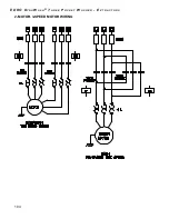
62/(12,'

/,*+7

127

86('

21/2:92/

7$*(

*51

%/.

%/8%/.

:+7

:+7%/.

25*%/.

25*

%/.:+7

%/.

%/.:+7

Summary of Contents for DW100

Page 1: ... to change without notice Manufactured in accordance to Canadian Standards Association general requirements The EDRO Corporation 37 Commerce Street P O Box 308 East Berlin CT 06023 0308 USA Tel 860 828 0311 Fax 860 828 5984 Web www edrocorp com Models DW100 DW150 DW200 DW300 DW400 Series DW DW_SM DW_PT DW_PTSM DW Range End Loading Rigid Mount DW_SM Range End Loading Soft Mount DW_PTSM Range Barrie...

Page 2: ...E D R O D y n a W a s h T h r e e P o c k e t W a s h e r E x t r a c t o r s 2 ...

Page 3: ...onable delay to remedy any defect found to exist under the terms of warranty During the warranty period parts found to be defective after the Seller s inspection will at the Seller s option be repaired or replaced with new or factory rebuilt parts free of charge except that of freight charges custom charges or other associated fees involved with the returning of the defective compo nent to the Sel...

Page 4: ...n 13 Elevation 14 Detergent Chemicals 14 Water Damage 14 SECTION 2 Installation 15 Rigid Mount Models DW DW_PT 15 Dyna Mount Soft Mount Models DW_SM DW_PTSM 15 PassThru Models DW_PT DW_PTSM 16 Foundation 16 Foundation Diagram Plan View 17 Grouting 19 Standard Plumbing Connections 19 Pneumatic Connections 19 Standard Electrical Connections 20 Service Connections 21 Plumbing 21 Electrical 21 Dyna Mo...

Page 5: ...g on Power Failure 28 Positioning Interlock Cylinder Jog 28 Door Lock 28 Emergency Stop 28 Vibration Switch 29 Customer Service 29 SECTION 4 Machine Operation 30 Before Operation 30 Loading 31 Automatic Operation 31 SECTION 5 Machine Configuration 33 Motor Setup 34 Water Level Setup 34 Ozone Signal Setup 34 Timers Setup 35 Miscellaneous Configurable Parameters 35 Language Setup 36 Programming 36 W...

Page 6: ...e 56 2 Motor Drive Models Only 57 Inverter with Single Motor Drive Models Only 57 Periodic Maintenance Requirements 57 Lubrication Diagram 58 Maintaining the Clutch 59 Installation 59 To replace discs or repair clutch 59 Maintaining the Brake 60 Installation 60 Lubrication 60 Maintenance 60 Inverter with Single Motor Drive Models Only 60 Maintaining the Bearings 61 Lubrication 61 Removal 61 Instal...

Page 7: ...y 83 Inner Door Assembly 84 Cylinder Assembly 85 Motor Assembly PassThru Models Only DW100PT 86 Motor Assembly PassThru Models Only DW150 DW200PT 87 Motor Assembly PassThru Models Only DW300PT 88 Motor Assembly PassThru Models Only DW400PT 89 Transfer Shaft Assembly PassThru Models Only 90 Drive Assembly 92 Brake Assemblies 93 Vibration Sensor 94 Vibration Switch 95 Pneumatic Assembly Standard 96 ...

Page 8: ...scussion of that procedure DANGER Identifies a condition which is not strictly observed could result in injury to or death to personnel WARNING Identifies an operating or maintenance procedure practice statement etc which if not strictly observed could result in injury to or death to personnel CAUTION Identifies an operating or maintenance procedure practice condition statement etc which if not st...

Page 9: ...the machine Do not allow children to play on or around this machine Do not leave children unattended while the machine door is open WARNING This machine must be installed adjusted and serviced by qualified electrical maintenance personnel familiar with the construction and operation of this type of machinery They must also be familiar with the hazards involved Failure to observe this warning may r...

Page 10: ... when the machine is in operation This warning symbol indicates the presence of possibly dangerous chemicals Proper precautions should be taken when handling corrosive or caustic materials This warning symbol indicates the presence of hot surfaces that could cause serious burns Steel and steam lines can become extremely hot and should not be touched Safety decals appear at crucial locations on the...

Page 11: ...an alarm should sound If the door lock and interlock are not functioning properly call a service technician Do not attempt to operate the machine if any of the following conditions are present a The door does not remain securely locked during the entire cycle b Excessively high water level is evident c Machine is not connected to a properly grounded circuit DO NOT BYPASS ANY SAFETY DEVICES IN OR O...

Page 12: ...ause personal injury For machines equipped with optional steam heating either direct or indirect install piping in accordance with approved commercial steam practices Failure to install the supplied steam filter may void the warranty Electric Heating Optional For best performance size the power source to the power rating of the heating element and in accordance with local codes A qualified electri...

Page 13: ...f questions regarding safety arise contact EDRO immediately END USER RESPONSIBILITY FOR ENVIRONMENT CONDITIONS Ambient Temperature Temperatures above 120º F 50º C will result in more frequent motor overheating and in some cases malfunction or premature damage to solid state components Special cooling devices may be necessary Increases and decreases in temperature affect water pressure switches Eve...

Page 14: ...e machine caused by corrosion resulting from the use of concentrated chemicals will impede machine performance and is specifically excluded from warranty DANGER Do not place volatile or flammable fluids in any machine Do not clean the machine with volatile or flammable fluids such as acetone lacquer thinners enamel reducers carbon tetrachloride gasoline benzene etc Doing so could result in serious...

Page 15: ...e a drain trough Models with drain to rear option are designed to be piped to a sewer drain It is required that all factory supplied mounting holes in the base footings of the machine be used to anchor the machine to the floor RIGID MOUNT MODELS DW DW_PT For installing DynaWash with Dyna Mount Soft Mount option DW100SM DW150SM DW200SM DW300SM DW400SM and DW100PTSM DW200PTSM DW300PTSM DW 400PTSM th...

Page 16: ...ure of the clean side seal goes between clean side of unit and barrier wall The clean side plate of the machine has bolts studded to it to assist in assembly of the barrier material from the machine to the barrier wall PASSTHRU MODELS DW_PT DW_PTSM It is vitally necessary to provide a proper foundation for DynaWash machines Anchor the machine to the floor by either pouring a new foundation in acco...

Page 17: ...MAXIMUM TRENCH WIDTH MAXIMUM TRENCH WIDTH DW End Loading Rigid Mount DW_PT PassThru Rigid Mount Plan View of Machine Footprint Machine Front DW DW_PT Dimension 100 150 200 300 400 A 23 30 30 35 1 2 43 B N A N A N A 47 1 2 55 C 47 54 54 59 1 2 67 D 31 32 5 8 39 5 8 49 1 4 49 1 4 Dimension 100 150 200 300 400 A 35 1 2 49 49 N A N A B N A N A N A N A N A C 59 1 2 73 73 N A N A D 27 7 8 29 36 1 8 N A ...

Page 18: ...150 200 300 400 A 82 88 90 92 100 B 38 41 5 8 48 3 8 57 57 DW_PTSM Dimension 100 150 200 300 400 A 92 99 101 102 3 8 108 B 38 40 5 8 47 3 8 57 55 NOTE Drawings reflect standard production models Options such as Electrical Right ER will effect foundation layout NOTE All dimensions are in inches NOTE To avoid alignment errors install foundation bolts after machine placement ...

Page 19: ...echeck that all nuts are tight Make periodically checks as follows 1 Daily for one 1 week 2 Weekly for one 1 month 3 Set up periodic inspection Section 6 DYNA MOUNT SOFT MOUNT MODELS DW_SM DW_PTSM Install Soft Mount models as in paragraph above Before loading and running the first cycle adjust the suspension system to the following measurements Bottom of front plate to base must be 1 1 4 and front...

Page 20: ...DW150 DW200 DW300 DW400 Wire Size 10 AWG 8 AWG 8 AWG 6 AWG 6 AWG Circuit Breaker 25 AMP 30 AMP 30 AMP 60 AMP 60 AMP NOTE Options such as Water Reuse System and Electric Heating Element will require larger wire sizes and must be determined at site by a qualified electrician Contact Factory for Electrical Connections not listed 2 MOTOR 3 SPEED DRIVE DW100 DW150 DW200 DW300 DW400 Wire Size 6 AWG 6 AW...

Page 21: ...he machine s electrical panel box Plumbing 1 The hot water inlet feeds the automatic supply injection system optional 2 EDRO supplies a valve for direct steam optional however all DynaWash machines are equipped with a built in muffler so steam can be injected manually or an automatically controlled valve can be added anytime in the future 3 All DynaWash machines are equipped with an air filter oil...

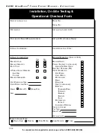
Page 22: ...ker Amp Size Voltage Machine Grounded Hot Water Line Size Cold Water Line Size Drain Open Pit Drain Pipe Size Machine Operation Check if O K Machine Empty Power On safety interlocks Unlock Open Door Run Test Program 50 Verify Operation Hot Water Cold Water Water Level Drain Dynozone Heat if applicable Rotation Standard Wash Forward Reverse Delicate Fluff Distribution Extract Clockwise Rotation Che...

Page 23: ... causes chemical particle entrapment within the garment fibers which cause yellowing of the garment during drying and finishing Too little chemical product per unit volume of water decreases chemical cleaning action Extraction is performed after the tub has been drained to remove large amounts of water from the clothing The extraction process is created by the acceleration of the cylinder from the...

Page 24: ... control components Chemicals may be added to the machine in a variety of methods The standard system sup plied with DynaWash consists of a manual hopper either located on the right side of the ma chine DW and DW_SM models or on the soiled side plate DW and DW_SM models and 10 ports for liquid supplies located on the right side of the machine A terminal strip located in the control panel provides ...

Page 25: ...undry have been well documented These systems provide a washing process that allows the laundry to be sterilized disinfected bleached and deodor ized with reduced water chemicals and heat However until now all ozone systems have been externally connected to washing machines require extra wiring floor and wall space and much maintenance to properly operate The DynOzone DynaWash Ozone System is diff...

Page 26: ...er consumption because the molecular energy of the gas replaces the energy of the heated water heat energy 2 It improves the hand or feel of the laundry because washing in cold water relaxes fibers and is not as harsh on the fibers as hot water and laundry chemicals such as bleach 3 It acts as an effective bleaching agent to brighten laundry This is due to the fact that singlet oxygen molecules ar...

Page 27: ...om end of each PowerCell Note that on some models you will need to remove panels to reveal the PowerCells These should be clean and free of lint in order to provide a free and clear path for the ambient room air to be drawn in and supercharged by the PowerCells It is a good idea to keep a few of these air filters on hand to avoid down time DYNOZONE DYNAWASH OZONE SYSTEM MAINTENANCE 2 Pump The spec...

Page 28: ...ATURES Electric Heat Generation uses a flange mounted electric immersion heater It is capable of increasing the temperature of the bath without the use of live steam Use of this heating element is for heating boost only The electric immersion heater is not intended for use as a sole source for hot water generation When in the operating mode the heating element must be submerged in the water Minimu...

Page 29: ...resume in the step it was last in before the error occurred and finish the program for that particular cycle For technical support or replacement parts contact the source from whom the washer extractor was purchased Contact EDRO DynaWash Service Department for the name and address of nearest authorized service and parts distributor Contact information is CUSTOMER SERVICE NOTE A record of each Dyna...

Page 30: ... interlocking safety devices which prevent the machine from being operated improperly it is advisable to check the condition of the machine before engaging the main switch Start Up Procedures Once the machine is set in place and service connections completed proceed with checking out the installation and operating functions making necessary corrections and adjustments Following are a few hints tha...

Page 31: ...an and flush the machine using hot water soap and alkali Place a few rags into each compartment Rinse with clean water Because of the patented 3 D cylinder construction of DynaWash the wash load should be divided into three equal parts not more than 10 difference in weights and between 95 and 105 of total rated capacity Best results are obtained when the load is kept within the machine s full rate...

Page 32: ...inue or browse with the navigation keys The DynaTrol touch screen control can be setup to work on any DynaWash washer extractor It must be properly configured to take full advantage of its capabilities Setup Machine Type and Parameters Configure Design and Edit Wash Programs Program Worker and Supervisor Modes Operation Managerial Productivity Reports Reports Information and Troubleshooting Techni...

Page 33: ...ns contain information on specific machine parameters which provide unique model characteristics They are broken down into the following sub sections Motor Setup Water Level Setup Ozone Signal Setup Timers Setup Miscellaneous Configurable Parameters NOTE A help button is located next to each parameter which further describes the necessary input or provides a means to set the value Enter or change ...

Page 34: ... MOTOR SETUP Configures motor design and speed settings for the machine Help Button WATER LEVEL SETUP Configures values which are affected by level sensing Click here to go to Water Level setup OZONE SIGNAL SETUP Configures DynOzone system and Signals working parameters Help Button ...

Page 35: ... r a c t o r s 35 TIMERS SETUP Configures values which are affected by timers MISCELLANEOUS CONFIGURABLE PARAMETERS Configures miscellaneous parameters Help Button Machines can be reloaded with factory default settings by going through the Settings Factory Process ...

Page 36: ...RAMMING The DynaTrol touch screen allows for the entry of up to 50 wash programs with 25 steps per program as well as the ability to link programs Wash programs may contain any of the following steps To enter Wash Programming press the Configuration button from the Home screen Then select the Wash Programming button A Level 2 password is required to enter Setup Water Rotation Signals and Time Wash...

Page 37: ...ndone From this screen you can create a program select a program to edit delete a program change program name return to previous menu or return to home screen The main wash programming screen contains six operations Wash Rinse Pause Extract Link Program Drain End Program Press the blue open button next to the operation you wish to perform A blue operation box indicates the current step function Fr...

Page 38: ...he Heat button will activate the heating device This setting will be maintained for the duration of the step ROTATION CONTROL The step programmable wash cadence is set to a default standard wash rotation By pressing the Rotation button a screen with six options will appear The setting is step local Available selections include Standard Wash Delicate Wash Fluff Forward Only Reverse Only No Rotation...

Page 39: ... can be configured to inject on a per step or global basis See Ozone Signal Setup Configuration for options Step Local Injection DRAIN STEP A Drain step may contain the following operations Sewer Drain Reuse Drain option Rotation control A time may be entered for a drain step DRAIN CONTROL Select either sewer drain or reuse Drain option LEVEL CONTROL Program a time and select level or select a wat...

Page 40: ...se Drain option A time must be entered for an extract step SPEED SELECTION Depending on motor configuration select a speed for extraction DRAIN CONTROL Select either sewer drain or reuse Drain option A Pause step may contain the following operations Pause Door Open Sewer Drain Reuse Drain option If door open is selected a drain must be selected to attain door open safety level ...

Page 41: ...PROGRAM Pressing the End Program button will delete all latter steps of the program PROGRAM SUMMARY When the Return button is pressed from the main wash programming screen a program summary will appear detailing all programmed steps Press the forward and reverse arrows to scroll through all 25 steps or Home or Return buttons to return to Configuration menu or programming screen ...

Page 42: ...is screen the function key Door is active to allow opening of the door for loading machine Press the Door button to activate door functions home button to return to home screen or Load button to go to Start screen Select the appropriate operation START begins program operation DOOR activates door lock screen AUTOSTART allows for starting the machine at a time in the future A popup screen contains ...

Page 43: ...els Door Screen Non Tilting Door Screen AUTOSTART The header includes current loaded program and program name The body contains present system time and settings for AutoStart time Select a day hour and minute to program and press ENABLE to activate Pressing Return button will deactivate AutoStart and go back to Start screen ...

Page 44: ...outputs The footer indicates step time and program time Pressing step time pops out a step view window of programmed step functions Times indicate remaining time Supervisor override button key halts machine operation for machine override functions The Override button allows changes to the following functions water level rotation temperature step time DynOzone step up or down heating end program Ac...

Page 45: ...cates the program number program name step number and step status The body contains bar graphs indicating current water level and current temperature and indicator for drain type A display indicates cylinder speed The footer indicates step time and program time Times indicate remaining time The override function is not available in an extract step PROGRAM COMPLETE At end of program a Program Compl...

Page 46: ...ged Machine sent to safe mode Reset component Alarm History screen appears with list of last 10 000 alarms List of Alarms Emergency Stop Low Air Supply Wash Motor Overload Ozone Pump 1 Failure Extract Motor Overload Ozone Pump 2 Failure VFD Overload PowerCell bank less than 50 Door Open During Operation Out of Balance Failure Sample Warning Water Level Timeout Machine sent to pause mode Reset time...

Page 47: ...tory of operation Alarms Counters Program History To view Reports press the Configure button from the Home screen then select Reports Alarms View current alarms alarm history and alarm frequency Counters View total machine hours and view and reset service timers Program History View last 10 000 programs run total times and cumulative data log with stop mode actions ...

Page 48: ...larms are active machine alarms Alarm History contains the last 10 000 alarms Alarm Frequency details the number of times a particular alarm occurred COUNTERS There are three counters These cannot be reset Total Machine Run Time counts hours of machine operation Total Programs Run counts total programs Power Cycles count On Off ...

Page 49: ... pop up screens and are re settable with password security PROGRAM HISTORY View the last 50 programs run with a time stamp and the total number of times for each Program Run Counters may be reset to zero by pressing the program count number and entering a Level 2 password On page 3 of the Run Counters a master reset is located as well as an Export to USB feature to move data out of the control ...

Page 50: ...or exporting in Microsoft Excel for viewing TECHNICAL INFORMATION DynaTrol provides several means for technical assistance and troubleshooting First each machine is configured with the Model Number and Serial Number on the Home screen Use this information whenever contacting EDRO technical support for assistance To enter DynaTrol s technical information section press the Configure button from the ...

Page 51: ...ion as interlocking safety features are disabled Do not wash clothes using the Debug Screens Debug Screen home page Select a range of inputs outputs for troubleshooting A red light will appear next to the active relays meaning the control circuitry is firing Refer to the machine schematic for X input and Y output descriptions The I O Lists illustrates all inputs and outputs of the control s PLC ex...

Page 52: ...proper configuration of System Doctor settings DynaTrol code settings allow for access to Password Management Water Temperature Settings Time and Date settings Control Software version Screen Calibration Copy and Transfer Programs Resetting of Factory Programs and Machine Configuration and USB Utilities for configuring media and off loading Report data CONTROL INFORMATION Displays the software ver...

Page 53: ... authority of level 2 and level 1 users and ability to change both level 2 and level 1 passwords Machines are shipped from the factory with the following passwords settings Level Description Default Password 0 User 00000000 1 Supervisor 11111111 Override Mode 2 Programmer 22222222 3 Maintenance 33333333 4 Owner 44444444 To change your password select Passwords from the Settings Home page and enter...

Page 54: ...red After copy function is complete copied program is fully editable CLEAR PROGRAM NAMES Clears all wash program names and reverts to Program 1 Program 2 Program 3 etc A level 2 password is required This action cannot be undone TRANSFER PROGRAMS Wash programs can be transferred from one HMI control to another either through cable connections or USB From Settings screen select USB or Cable connecti...

Page 55: ...w screen instructions formodel specific machine characteristics RESET FACTORY PROGRAMS Resets wash programs to factory defaults A level 2 password is required This action cannot be undone DEFAULT FACTORY PROGRAMS 1 Light Soil Ozone 11 Light Soil 2 Light Soil Ozone 12 Light Soil 2 3 Medium Soil Ozone 13 Medium Soil 4 Medium Soil 2 Ozone 14 Medium Soil 2 5 Heavy Soil Ozone 15 Heavy Soil 6 Delicates ...

Page 56: ...ade and the bolts and nuts tightened if found loose This is due to the setting of the machine in place as well as expansion from heat and motion Keep checking the following The floor bolts must be kept tight and checked periodically The nuts on the front plate may come loose from the softening of the gasket and should be gone over at least once even though no leaks develop Check the taperlock bush...

Page 57: ...ry six months 2 Motor Drive Models Only Motors should be greased only once a year Drain water from air filter and refill oil jar as needed Keep belts tight especially on wash motor PERIODIC MAINTENANCE REQUIREMENTS 2 Motor Drive Models Only Below Check at least once the similar taper bushing screws on the clutch as they have a tendency to loosen up from heat and constant jogging The initial wear o...

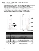
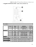
Page 58: ...ure water resistant lithium grease DW150 DW400 with 2 Motor Drive Models ONLY Change oil in gear reducer Item 7 every six 6 months Use SHC634 SYNTHETIC GEAR OIL Adjust oil regulator See Item 5 to permit one 1 drop of oil every five 5 minutes Refill with S A E No 10 as needed Drain filter bowl as required LUBRICATION DIAGRAM Item Description 1 Rear Bearing 2 Extract Motor 3 Wash Motor 4 Front Beari...

Page 59: ...ates for foreign matter burrs or wear The front and center drive plates must move freely on drive hub hex for proper release Check friction disc lugs in pulley slots for freedom of movement When assembling lightly coat the drive hub hex with a moly type grease Take care not to get grease on the face of the steel drive plates or friction discs Replace rubber U cup in air cylinder if torn or worn fr...

Page 60: ...embly on both sides of the disc Use 3 8 diameter bolts to mount the T support to a solid base on the machine s motor plate Each air chamber is tapped 1 8 NPT for air connection Lubrication All pneumatic devices require clean pressure regulated and lubricated air for maximum performance and long life Use of an air line filter regulator and lubricator on the air line is standard on all DynaWash mach...

Page 61: ...dingly Watch operation temperatures Sudden rises may show need for grease or indicate over lubrication Use grade 2 high temperature water resistant lithium grease Removal Front Bearing remove bearing cover and grease line from grease fitting Rear Bearing remove belt guard belts and flywheel Proceed by removing mounting bolts and place them into existing tapped holes on the bearing flange Use bolts...

Page 62: ...ure then tap evenly all around until seated or flush with housing face Tap only on outer edge of seal NOTE Lubricate shaft and lip of seal Always clean cavity and shaft when replacing seals or bearings WARNING Never cut solid seals for adjustment to fit on shaft Model DW100 DW150 DW200 DW300 DW400 Shaft Size 2 3 3 3 3 Collar Set Screws 680 in lbs 680 in lbs 680 in lbs 680 in lbs 680 in lbs Mountin...

Page 63: ...consistent with rules stored in the control s ladder logic program The ladder logic and its internal rules and instructions thus combine to form an all electronic control able to monitor and more importantly manage every operating aspect of the machine PRELIMINARY TROUBLESHOOTING The HMi DynaTrol is fitted with a multitude of warning and alarm screens for notification of most machine symptoms and ...

Page 64: ...g of the operation of the machine corresponding to the programmed formulas i e knowing what the machine is supposed to be doing at a certain point in the formula and why If an output such as a solenoid valve motor contactor etc is not activated and the corresponding Y output indi cator light is off indicating the output terminal is not energized you must search backwards to determine what conditio...

Page 65: ... Sensor X40 Jog WS X41 Powercell 7 X42 Powercell 8 X43 E Stop 2 X44 E Stop 3 X45 E Stop 4 X46 FWD Tilting Bearing Locked X47 FWD Tilting Bearing UnLocked X50 REV Tilting Bearing Locked X51 REV Tilting Bearing UnLocked X52 Index Proxy Sensor X53 Thermguard Switch Extract MTR X54 Index Switch PB CS X55 Forward CS X56 Reverse CS X57 Switch 0 X60 Switch 1 X61 Lock WS X62 Job CS X63 Signal WS X64 PT CS...

Page 66: ... valve Defective drain control relay output H Cylinder does not reverse rotates in one direction with long pauses during wash steps Defective reversing contactor Defective reverse control relay output I Program does not advance Loose or broken wires Defective level switch J 2 Motor Drive motor does not operate Motor overheated Defective motor K 2 Motor Drive motor goes on and off er ratically in b...

Page 67: ...programmed incorrectly reduce load if material is very water absorbent Loss of speed command voltage at terminal drive check DC voltage between points D A CHø VO zero and less than 10 VDC for the drive to ac celerate the motor S Inverter w Single Motor Accelerates too fast Acceleration parameters of drive or control is set incorrectly Check parameters for agreement with factory settings T Inverter...

Page 68: ...OM plug not fully seated Check for tightness Disconnected wire in the communication Check for disconnected wire on the PLC side of the cable Verify correct voltage terminals on transformer AB No power to PLC Green power light not on Check for 220VAC power to the power supply Check the power plug from the power supply to the PLC Remove the 24VDC and 0VDC wires from the power supply and repower wash...

Page 69: ...he clean room side are the opening of the door on that side the positioning of the cylinder compartments by use of the Jog buttons and Emergency Stopping Indicators on each operator s panel show which side is currently in control Neither access door can be opened unless the other side has its door securely closed and releases control of the machine PASSTHRU MODELS ONLY DYNATROL PASSTHRU Access Pas...

Page 70: ...time to align a pocket Press the JOG button and FORWARD or REVERSE buttons to correct any misalignment 5 Open the pocket door and load the pocket Close the pocket door 6 Repeat steps 4 and 5 until all three pockets in the machine are loaded 7 Close the access door 8 Select a program number press load program to go to start screen Press the START button to begin machine operation 9 At end of the pr...

Page 71: ...he door handle 3 If machine is equipped with Auto Index press and hold the JOG and INDEX buttons at the same time to align a pocket Press the JOG button and FORWARD or REVERSE buttons to correct any misalignment If not equpped with Auto Index then just press JOG and FORWARD or REVERSE to align pockets 4 Open the pocket door and unload the pocket Close the pocket door 5 Repeat steps 3 and 4 until a...

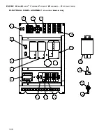
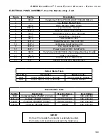
Page 72: ...2 3 8 2 Figure Part No Description Qty 1 6092 Buzzer 24 V C 120 DB 1 2 6292 1 Block Contact 4 3 6296 Operator Momentary Double 1 4 6298 Legend Cap Forward 1 5 6298 1 Legend Cap Reverse 1 6 6301 Operator Switch Push Button 2 7 6302 Legend Lens Jog 1 8 6303 Legend Lens Index 1 9 6537 33 USB Socket 1 10 6537 TS7 Touch Screen Control 7in 1 11 6640 Contact Block NO NC 1 12 6831 Switch Operater Momentar...

Page 73: ...omentary Signal 1 4 6609 1 Light Indicator Red 1 2 RD 1 5 6301 Operator Switch Start Push Button 2 6 6292 1 Block Contact 4 7 6092 Buzzer Audio 120 DB 24 VAC 1 8 6298 Legend Cap Forward 1 9 6298 1 Legend Cap Reverse 1 10 6302 Legend Lens Jog 1 11 6303 Legend Index 1 12 6640 Contact Block NO NC 1 13 6831 Switch Operator Push Pull 1 14 6832 Button Emergency Stop 1 15 6296 Operator Momentary Double 1...

Page 74: ...t Dump Cover 1 4 1133 610 Plate Top Drain B P 1 5 1132 610 Gasket Seal B P 1 6 1131 610 Plate Bottom Drain 1 Figure Part No Description Qty 1 1130 Air Cylinder 1 1 16 Dia X 6 Stroke Thread Mount 1 2 1134 Gasket Drain Air Cylinder 1 3 1117 1 1520 Gasket Drain Cover B P 1 4 1133 1520 Plate Top Drain 1 5 1132 1520 Gasket Seal B P 1 6 1133 610 Plate Top Drain B P 1 Figure Part No Description Qty 1 113...

Page 75: ...rt No Description Qty 1 1130 Air Cylinder 1 1 16 Dia X 6 Stroke Thread Mount 1 2 1134 Gasket Drain Air Cylinder 1 3 1117 1 610 Gasket Dump Cover 1 4 1133 610 Plate Top Drain B P 1 5 1132 610 Gasket Seal B P 1 6 1131 610 Plate Top Drain B P 1 Figure Part No Description Qty 1 1130 Air Cylinder 1 1 16 Dia X 6 Stroke Thread Mount 1 2 1134 Gasket Drain Air Cylinder 1 3 1117 1 1520 Gasket Drain Cover B ...

Page 76: ...o Description Qty 1 1515 1 10C Seal Bearing Adapter 2 2 S10C 1515 2 Sleeve Speedi 2 1 2 ID 1 3 1509 10C Gasket Bearing 1 4 9757 Bolt Hex Head 4 5 9560 Washer Lock Half Plated 4 6 7 13 1501 10C Bearing Slotted 1 8 7022 Elbow Male 1 9 7021 Tubing Copper 1 10 7023 Connector Straight 1 11 12 1530 1 Block Grease Fitting 1 ...

Page 77: ...her Lock Half Plated 4 6 7 13 1501 1520 Bearing Slotted 1 8 7022 Elbow Male 1 9 7021 Tubing Copper 1 10 7023 Connector Straight 1 11 12 1530 1 Block Grease Fitting 1 Figure Part No Description Qty 1 1515 3040 Seal Bearing Adapter 2 2 S3040 1515 2 Sleeve Speedi 2 1 2 ID 1 3 1509 3040C Gasket Bearing 1 4 9729 1 Bolt Hex Head 4 5 9563 Washer Lock Half Plated 4 6 7 13 1501 3040C Bearing Slotted 1 8 70...

Page 78: ...4 Tee Bronze 2 X 2 X 3 4 1 2 3311 1234 Nipple Close 2 NPT Brass 1 3 3271 Bushing Reducing 3 4 NPT M X 1 4 NPT F Brass 1 4 7014 Nipple Hex 1 4 NPT Brass 1 5 7164 Valve Water Gate 1 4 NPT Bronze 1 6 7003 Elbow M X F 1 4 NPT X 90 Brass 1 7 3193 Adapter Brass 3 8 Hose X 1 4NPT 22 8 3194 Hose 3 8 ID 200 PSI 212 F 15 FT 9 3235 Valve Water 2 Way 1 4 NPT 24VAC 5 10 3008 Manifold Supply B P 1 11 3196 Fitti...

Page 79: ...urfaces that could cause serious burns Steel and steam lines can become extremely hot and should not be touched SHSRK 2192 75 Repair Kit for DW 100 3340 Direct Steam Valves Includes Piston Assembly Plunger O Rings Seat Washer Teflon Rings SHSRK 2192 75 Repair Kit for DW150 200 300 400 3428 Direct Steam Valves Includes Piston Assembly Plunger O Rings Seat Washer Teflon Rings Figure Part No Descript...

Page 80: ...ion Qty 1 3434 Strainer Bronze 3 4 NPT 1 2 3036 Nipple Close Bronze 3 4 NPT 3 3 3340 Valve Steam 3 4 NPT 24VAC 1 4 3430 610 Coil Tank Heater Steam 1 5 3036 1 Nipple Close 3 4 NPT 316SS 2 6 3035 Elbow 3 4 NPT X 90 316SS 1 7 3436 Trap Steam 3 4 NPT Cast Iron 1 8 3037 Union Bronze 3 4 NPT 1 9 3435 Bushing Reducing 1 1 4 NPT M TO 3 4 NPT F 304SS 1 8 2 2 1 3 9 6 7 5 5 4 ...

Page 81: ...xtremely hot and should not be touched SHSRK 2192 1 25F Repair Kit for DW150 200 300 400 3428 In Direct Steam Valves Includes Piston Assembly Plunger O Rings Seat Washer Teflon Rings INDIRECT STEAM INJECTION CONTINUED Figure Part No Description Qty 1 3429 Strainer Bronze 1 1 4 NPT 1 2 3311 1 610 Nipple Close Bronze 1 1 4 NPT 3 3 3428 Valve Steam 1 1 4 Bronze 1 4 3430 3040 Coil Tank Heater Steam 1 ...

Page 82: ...4 ROD SPRING LATCH SIDE 6 4055 1234 ROD SPRING HINGE SIDE 7 2423 SPRING 3 8 I D X 2 LG 8 4004 1234 GASKET MAIN DOOR 3 4 RD X 1 8 FL 9 6269 1 ACTUATOR PROXIMITY SWITCH Fig Part No Description DW100 DW150 DW200 DW300 DW400 1 4050 610 Main Door Assembly Spring Loaded X 4050 1520 Main Door Assembly Spring Loaded X X 4050 30Y Main Door Assembly Spring Loaded X 4050 40E Main Door Assembly Spring Loaded ...

Page 83: ... 1 6 4155 Cover Door Latch Body 1 7 9572 Washer Flat 3 8 SAE SS 2 8 6813 Light Indicator Clear 24VAC 1 9 6268 3 Clip Spring Retainer B P 1 10 6268 4 Spring Door Lock Shaft B P 1 11 6269 Switch Proximity Hermetic 1 12 9568 Clip Retaining Light Indicator 1 13 6090 1 Switch Latch Box 1 14 2423 Spring 3 8 I D X 2 LG 1 15 6268 1 Solenoid Door LOCK 24VAC 1 16 9626 2 Screw RD HD 4 40 X 5 8 1 17 9594 Scre...

Page 84: ...ESE COMPONENTS ARE COMMON TO ALL INNER DOOR ASSEMBLIES 6 2423 SPRING 3 8 I D X 2 LG 7 2424 HANDLE INNER DOOR 8 9605 SCREW SHOULDER Ø1 4 X 3 8 X 10 24 9 9537 2 NUT HEX NYLON 10 24 SS INNER DOOR ASSEMBLIES ARE MARKED WITH THE POCKET NUMBER TO INDICATE THE Cylinder POSITION PLEASE BE SURE TO ORDER THE CORRECT DOOR NUMBER FOR REPLACEMENT 1 2 OR 3 Fig Part No Description DW100 DW150 DW200 DW300 DW400 1...

Page 85: ...0SM 2000 30PT CYLINDER ASSEMBLY DW300PTSM 2000 40E CYLINDER ASSEMBLY DW400 DW400SM 2000 40PT CYLINDER ASSEMBLY DW400 40PTSM USE IN MACHINES WITH A 2 MOTOR DRIVE SYSTEM Use in machines with a 2 motor drive system DW Series Cylinder Assemblies Part No Description Machine Series 2000 10C Cylinder Assembly DW100 DW100SM 2000 10PT Cylinder Assembly DW100PT DW100PTSM 2003 15H Cylinder Assembly DW150 DW1...

Page 86: ... complete model and serial number off brake Figure Part No Description Qty 1 5400 Wash Motor 1 2 5830 610 Belt Main Drive Not Shown 1 3 5311 10PT Bushing Extract 1 1 8 Bore SDS 1 4 5310 10PT Sheave Extract 2A4 2B4 6 SDS 1 5 5731 610 Disc Brake 5 16X12 B P 1 6 5729 Brake Assembly Unit 1 7 5300 Extract Motor 1 8 5600 1 610 Spare Part Air Clutch Kit 1 9 5860N 610 Belt Wash Motor B 46 2 10 5410N 610 S...

Page 87: ...number Figure Part No Description Qty 1 5300 Motor Extract 1 2 5400 1520 Motor Wash 2 HP 1 3 5410 1520 Sheave Wash 3V3 35 TL 1 GR 1 4 5411 1520 Bushing Wash 1610 X 7 8 TL 1 5 5840 1234 Belt Wash Motor 3VX250 2 6 5510 1520 Sheave Reducer 3V5 0 TL 1GR 1 7 5411 1520 Bushing Wash 1610 X 7 8 TL 1 8 5500 1520 Reducer Gear 1 9 5600 1520 Clutch Air 1 10 5310 1520PT Sheave Extract 4A5 6 B6 0 TL 1 10 5310 5...

Page 88: ...3 5410 3040 Sheave Wash 2GR 3V3 0 TL 1 4 5411 3040 Bushing Wash 1210 X 1 1 8 1 5 5840 1234 Belt Wash Motor 3VX250 2 6 5510 3040 Sheave Reducer 3V4 5 2GR TL 1 7 5511 3040 Bushing Taper Lock 1610 X 1 3 16 1 8 5500 3040 Reducer Gear 1 9 5600 3040 Clutch Air 1 10 5310 30PT Sheave Extract 5V7 5P 3GR 1 11 5311 3040 Bushing Extract E X 2 0 1 12 5830 30Y Belt Main Drive Not Shown 3 13 5743 30PT Belt Drive...

Page 89: ...Part No Description Qty 1 5300 Motor Extract 1 2 5400 3040 Motor Wash 3HP 220 380 50 1 3 5410 3040 Sheave Wash 2GR 3V3 0 TL 1 4 5411 3040 Bushing Wash 1210 X 1 1 8 1 5 5840 1234 Belt Wash Motor 3VX250 2 6 5510 3040 Sheave Reducer 3V4 5 2GR TL 1 7 5511 3040 Bushing Taper Lock 1610 X 1 3 16 1 8 5500 3040 Reducer Gear 1 9 5600 3040 Clutch Air 1 10 5310 30Y Sheave Extract CQ9 5 QD 3GR 1 11 5311 3040 B...

Page 90: ...ransfer B P 1 4 5740 10PT Bearing Pillow Block 2 2 5 5748 10PT Flywheel 2A10 6B11 0 SK 1 6 5749 10PT Bushing SK X 2 O BORE 1 7 5747 10PT Belt Transfer Drive 3VX800 6 8 5830 10PT Belt Main Drive B 89 4 Figure Part No Description Qty 1 5746 1520PT Bushing SK X 2 1 2 BORE 4 2 5745 1520PT Sheave 3BQ7 0 3GR 4 3 5741 15PT Shaft Transfer B P 1 3 5741 20PT Shaft Transfer B P 1 4 5740 1520PT Bearing Pillow...

Page 91: ...2 5 5748 30PT Flywheel 5V21 2 3GR QD 1 6 5746 40PT Bushing E X 2 1 2 Bore 1 7 5747 30PT Belt Transfer Drive 5VX1180 6 8 5743 30PT Belt Drive 5V 1320 3 Figure Part No Description Qty 1 5746 40PT Bushing E X 2 1 2 Bore 4 2 5744 40PT Sheave 4GR 5V10 3 QD 2 3 5741SM 3040PT Shaft Transfer B P 1 4 5740 1520PT Bearing Pillow Block 2 1 2 2 5 5748 40PT Flywheel 5V21 2 4GR QD 1 6 5746 40PT Bushing E X 2 1 2...

Page 92: ...0 5830 6 5 BUSHING FLYWHEEL 5702 3040 5702 3040 5702 1520 5702 1520 5702 1 6 FLYWHEEL 5701 3040 5701 3040 5701 1520 5701 1520 5701 6 7 BRAKE ASSEMBLY 5729V 3040 5729V 3040 5729V 1520 5729V 1520 5729V 6 Item Part Description DW100 DW100SM DW150 DW150SM DW200 DW200SM DW300 DW300SM DW400 DW400SM 1 Motor Extract 5300 1E 85X 5300 1E 20M 5300 1E 20M 5300 1E 30Y 5300 15E 40E 2 Sheave Motor 5315 14XP 5310...

Page 93: ... 2 1 3 3 2 DW DWSM 300 DW DWSM 400 1 1 DW DWSM 150 DW DWSM 200 2 3 2 DW DWSM 300 DW DWSM 400 1 DW100 DW100SM DW150 DW150SM DW200 DW200SM DW300 DW300SM DW400 DW400SM Item Description DW100 DW100SM Qty DW150 DW150SM DW200 DW200SM Qty DW300 DW300SM DW400 DW400SM Qty 1 Brake Assembly 5729V 610 1 5729V 1520 2 5729V 3040 2 2 Tee Male Branch Swivel 7036 1 7036 2 7036 2 3 Elbow Male Brass 7002 1 7002 2 70...

Page 94: ...e To adjust the sensor sensitivity loosen mounting bracket and tilt switch forward or backward The further away from horizontal the sensor body is the less sensi tive it becomes and the closes to horizontal it is the sensor is more sensitive Test the sensor with the machine fully installed leveled and bolted in place Run a full load in high extract moni toring excessive vibration during operation ...

Page 95: ...ch can be adjusted both vertically and horizontally The vibration rod should be centered in the bracket s hole For proper adjustment the screws can be loosened allowing the rod to slide up or down within the bracket To adjust horizontally the vibration rod should be 1 4 from the head of the bolt Either tighten or loosen the screw to attain proper measure This vibration switch will trip off the mac...

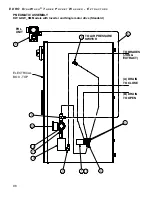
Page 96: ... NO PART NU 1 3060 2 6700 3 7002 4 7006 5 7012 6 7028 7 7029 8 7036 9 7121 10 7150 11 7150 2 12 7172 13 7173 10 1 11 9 6 4 13 7 12 8 3 FRL SWITCH A DRAIN TO CL UNIT B DRAIN TO OP TOP TO AIR PRESSURE TO BRAKES JOG 3 ELECTRICAL BOX 5 9 ELECTRICAL BOX TOP 4 13 12 7 10 3 1 11 4 3 5 6 TO AIR PRESSURE SWITCH FRL UNIT TO BRAKES JOG EXTRACT A DRAIN TO CLOSE B DRAIN TO OPEN ...

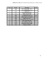
Page 97: ...002 Elbow Male Brass Swivel 8 NPT X 1 4 OD Tube 3 4 7006 Tee Male Run 1 4 X 1 4 1 5 7012 Tubing Polyt Air 1 4 OD X 180 35 FT 6 7028 Elbow Female 1 4 X 1 8 Brass 1 7 7029 Nipple Reducer Hex 1 8 7036 Tee Male Branch 1 4 X 1 4 X 1 8 NPT 1 9 7121 Filter Air Regulator FRL 1 10 7150 Valve Solenoid 3 Way 24V 1 11 7150 2 Valve Solenoid Drain 4 Way 1 12 7172 Regulator Air Range 125PSI 1 13 7173 Gauge Air 0...

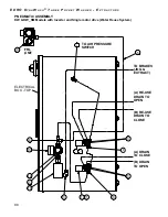
Page 98: ... BRAKES JOG EX TO AIR PRESSURE SWITCH A DRAIN TO CLOSE B DRAIN TO OPEN 6 A RE USE DRAIN TO O 9 B RE USE DRAIN TO C 8 8 3 10 7 12 13 4 11 1 3 1 11 3 ITE NO 1 2 3 4 5 6 7 8 9 10 11 12 13 FRL UNIT TO BRAKES JOG EXTRACT TO AIR PRESSURE SWITCH FRL UNIT A RE USE DRAIN TO OPEN B RE USE DRAIN TO CLOSE A DRAIN TO CLOSE B DRAIN TO OPEN 9 4 13 12 7 10 3 1 11 8 3 3 8 5 ELECTRICAL BOX TOP ...

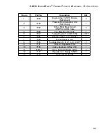
Page 99: ...002 Elbow Male Brass Swivel 8 NPT X 1 4 OD Tube 5 4 7006 Tee Male Run 1 4 X 1 4 1 5 7012 Tubing Polyt Air 1 4 OD X 180 45 FT 6 7028 Elbow Female 1 4 X 1 8 Brass 1 7 7029 Nipple Reducer Hex 1 8 7036 Tee Male Branch 1 4 X 1 4 X 1 8 NPT 2 9 7121 Filter Air Regulator FRL 1 10 7150 Valve Solenoid 3 Way 24V 1 11 7150 2 Valve Solenoid Drain 4 Way 2 12 7172 Regulator Air Range 125PSI 1 13 7173 Gauge Air 0...

Page 100: ...on located on the control panel at the same time This will cause the cylinder to rotate to the next compartment position and stop automatically The two buttons must be released and the sequence repeated to advance to the next compartment and so on Figure Part No Description Qty 1 6268 1 Solenoid Door Lock 24VAC 1 2 6268 4 Spring Door Lock Shaft B P 1 3 6268 3 Clip Spring Retainer B P 1 4 7212 1234...

Page 101: ...s reqd 3 9636 Bolt Hex HD 5 8 11 X 3 Partial Thread GR8 Zinc as reqd Not Shown 9576 1 Washer Flat 21 32 ID x 1 5 16 OD as reqd 9545 Nut Hex 5 8 11 Plated as reqd 9552 Nut Jam 5 8 11 NC as reqd 9668 Nut Flex 1 8 NC Plated 4 9555 1 Nut Jam 1 8 NC STD 4 9555 2 Nut Hex 1 8 NC Plated 4 DW100SM 2 8165 610 Spring Mounting 750 4 DW150SM DW200SM 2 8165 1520 Spring 6 O D X 10 5 LG X 1235 4 DW300SM DW400SM 2...

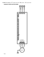
Page 102: ... n a W a s h T h r e e P o c k e t W a s h e r E x t r a c t o r s 102 VARIABLE SPEED MOTOR WIRING VARIABLE MA MOTOR R T3 T1 T2 FREQUENCY DRIVE VFD SN S2 S1 MC A1 S T R S T R S T U V W AC S7 SC SP S6 3 S3 L1 L2 L3 ...

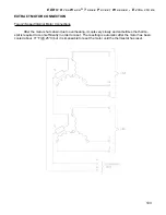
Page 103: ...Internal Motor Connections After the motor shuts down due to overheating it cools very slowly and sometimes the thermo stat is required to cool sufficiently in order to reset The resetting is automatic after the motor has been cooled about 77 F 25 C but it is impossible to reset the motor until the thermostat has reset ...

Page 104: ...E D R O D y n a W a s h T h r e e P o c k e t W a s h e r E x t r a c t o r s 104 2 MOTOR 3 SPEED MOTOR WIRING ...

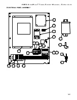
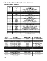
Page 105: ...AL 3 POLE 1 4 6825 1 CONTACTOR 50AMP 24V 1 5 6581 G GROUNDING TERMINAL 2 6 6660 TRANSFORMER 100VA PRI 208 240 277 380 480 SEC 24 1 7 6380 11 FUSE 3 AMP 600V 1 8 6685 TRANSFORMER 240 480 500VA HIGH VOLTAGE MACHINES ONLY 1 9 6270 SWITCH AIR PRESSURE 1 10 6537 8 PRESSURE SENSOR WATER LEVEL 1 11 7001 1 ADAPTOR FEMALE PIPE 1 12 6266 RELAY MINIATURE DPDT 24 V AC 1 13 6266 1 RELAY SOCKET 2 POLE 1 14 6385...

Page 106: ...amps Black 17 6361 3 Terminal Blocks Single Level Feed Through 18 6537 3 I O Module DynaTrol ELC EX 19 6537 2 PLC DynaTrol ELC PA 20 6537 1 Power Supply 24VDC DynaTrol 1A 21 See Brake Resistor Table Inverter Table Part No Description Machine Series Voltage Motor HP 6759 Inverter VFD 7 5HP 230VAC DW100 208 240VAC 7 5HP 6759 1 Inverter VFD 7 5HP 480VAC DW100 380 480VAC 7 5HP 6760 3 Inverter VFD 15HP...

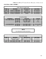
Page 107: ...300 DW400 380 480 VAC 6825 2 Contactor 120 AMP 24V DW400 208 240 VAC Circuit Fuse Table Configuration Part No Description Locations High Voltage 380 480 6380 2 Fuse 5 AMP 250V F3 F5 6380 7 Fuse 3 AMP 250V F4 6380 11 Fuse 3A 600V F1 F2 Low Voltage 208 240 6380 2 Fuse 5 AMP 250V F1 F2 F4 F5 6380 7 Fuse 3 AMP 250V F3 Brake Resistor Table Part No Description Machine Series Input Voltage 6679 6 Resisto...

Page 108: ... NUMBER DESCRIPTION QTY 1 6660 TRANSFORMER 100VA PRI 208 240 277 380 480 SEC 24 1 2 See Note STARTER 2 3 6266 RELAY MINIATURE DPDT 24 V AC 2 4 6581 G GROUNDING TERMINAL 2 5 6431 2 BLOCK POWER TERMINAL 3 POLE 1 6 6385 BLOCK SAFETY FUSE 2 POLE 600 VOLT 1 7 6405 TERMINAL BLOCK 71 8 6415 TERMINAL END CAP 5 9 6461 STARTER REVERSING SIZE 0 1 10 6537 3 I O MODULE 5 13 14 15 16 ...

Page 109: ...End 9 6461 4 Starter Reversing Size 0 24 VAC 10 6537 3 I O Module DynaTrol ELC EX 11 6537 2 PLC DynaTrol ELC PA 12 6537 1 Power Supply 24VDC DynaTrol 1A 13 6685 Transformer 240 480 500VA High Voltage Machines Only 14 6270 Switch Air Pressure 15 6537 8 Pressure Sensor Water Level 16 7001 1 Adaptor Female Pipe Brass Barbed Extract Starter Table Part No Description Machine Series 6462 Starter Extract...

Page 110: ...56 5 1 56 9 9 0 76 81 66 27 5 6 63 5 7 216 0 6 1 6 0 187 6 685 6 2 127 6 5 1 6 33529 5 9 1 02 7 7 7 6 3 57 180 5 6 7 5 1 75 6 0 7 121 2 7KH 52 RUSRUDWLRQ RPPHUFH 6WUHHW DVW HUOLQ 7 86 5 87 25 7 21 25 86 7KLV GRFXPHQW LV DXWKRUL HG IRU XVH DV VSHFLILHG E WKH 52 253 R QRW XVH SUHYLRXV UHYLVLRQV ZLWKRXW DSSURYDO XWKRUL HG E BBBBBBBBBBBBB DWH BBBBBBBBBBBBBBBBBBBBB 35235 7 5 1 21 17 7KH LQIRUPDWLRQ FRQ...

Page 111: ... ONE TIME CENTER OF SENSOR WIRE PASSES THROUGH SWITCH CURRENT AIR PUMP 1 OZONE LAMP 2 BALLAST OZONE LAMP RED PAIR BLUE PAIR GREEN LAMP 2 CURRENT SWITCH OZONE LAMP 3 BALLAST OZONE LAMP RED PAIR BLUE PAIR GREEN LAMP 3 CURRENT SWITCH OZONE LAMP 4 BALLAST OZONE LAMP RED PAIR BLUE PAIR GREEN LAMP 4 CURRENT SWITCH OZONE LAMP 5 BALLAST OZONE LAMP RED PAIR BLUE PAIR GREEN LAMP 5 CURRENT SWITCH OZONE LAMP ...

Page 112: ... Circuit Breaker Amp Size Voltage Machine Grounded Hot Water Line Size Cold Water Line Size Drain Open Pit Drain Pipe Size Machine Operation Check if O K Machine Empty Power On safety interlocks Unlock Open Door Run Test Program 50 Verify Operation Hot Water Cold Water Water Level Drain Dynozone Heat if applicable Rotation Standard Wash Forward Reverse Delicate Fluff Distribution Extract Clockwise...

Reviews: