14
ENGLISH
3
1
2
4
5
6
7
8
9
a
b
10
a
a
a
a
INSTALLER
STEEL CLADDING
Description
Reference in the figures below
Quantity
Top left-hand side
(1)
n°1
Top left-hand side panel with pre-cutting for side
fume discharge
(2)
n°1
Upper right side
(3)
n°1
Lower right side
(4)
n°1
Upper central profile
(5)
n°1
Lower central profile
(6)
n°1
Left outline
(7)
n°1
Left front outline
(8)
n°1
Right depth
(9)
n°1
Side smoke outlet rosette
(10)
n°1
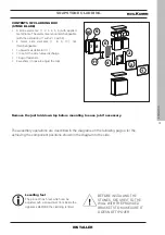
Small hardware
Countersunk hex screw M5x16
(a)
n°15
Self-tapping screw 4,2x9,5
(c)
n°9
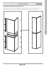
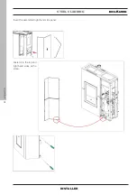
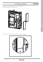
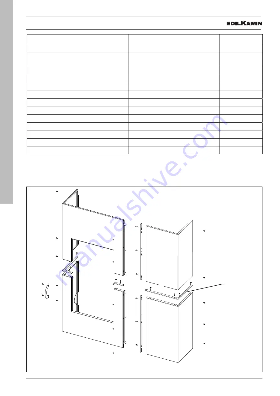
The above-mentioned elements, once they have been mounted, will be positioned (“exploded”) as shown in the figure
The above-mentioned elements, once they have been mounted, will be positioned (“exploded”) as shown in the figure
below. The mounting operations are described in the figures appearing on the following pages.
below. The mounting operations are described in the figures appearing on the following pages.
“Right” and “left” refer to the product when viewed from the front.
“Right” and “left” refer to the product when viewed from the front.
Summary of Contents for Blade2 12 Up
Page 61: ...61 ENGLISH MAINTENANCE 4 2 1 USER Position correct Position incorrect deflector Cross section ...
Page 69: ...69 ENGLISH ...
Page 70: ...70 ENGLISH ...
Page 71: ...71 ENGLISH ...


