background image

55

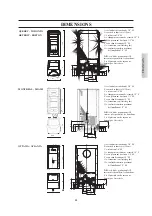
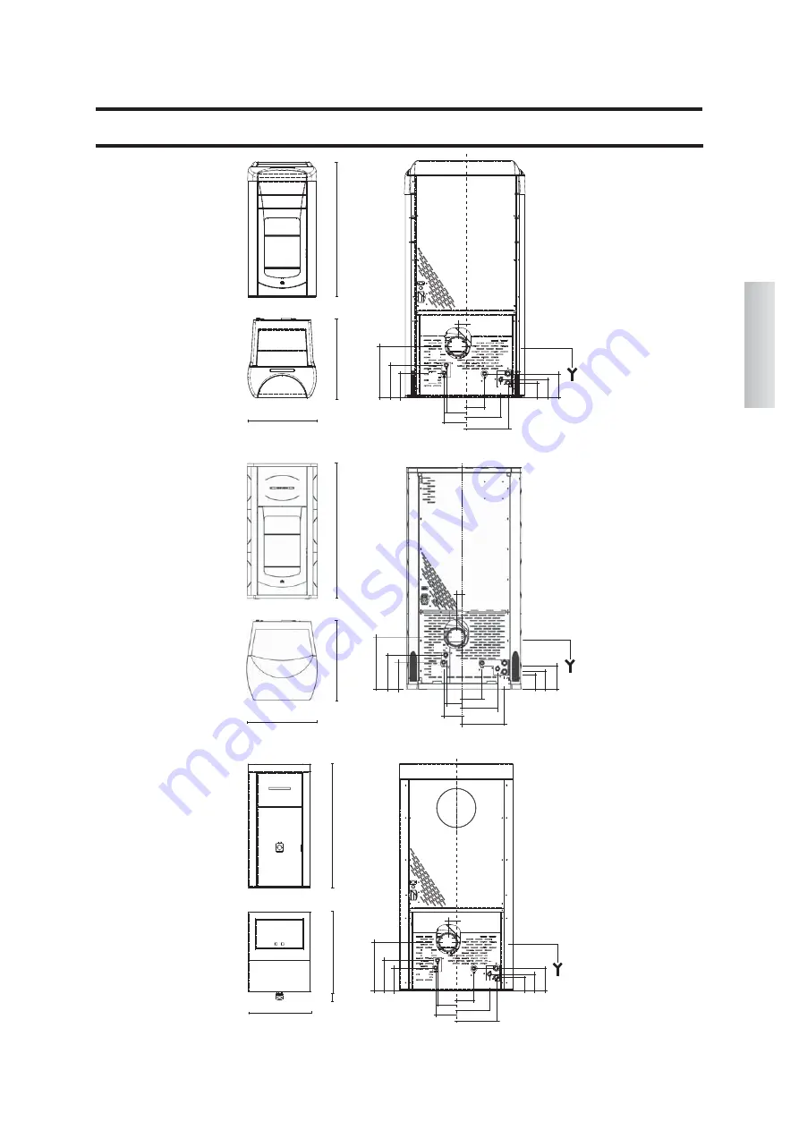
DIMENSIONS

=

refoulement eau chaude 3/4” M

sortie des fumées (Ø 10 cm)

C

retour eau 3/4” M

D

échappement vanne de sécurité 1/2” F

E

eau provenant du réseau 1/2” M

F

eau chaude sanitaire1/2” M

G

évacuation eau (latérale gche)

H

eau froide sanitaire provenant

de l'installation 1/2” M

N.B.:

si le kit de production ACS 

interne n'est pas utilisé, les bouchons 
F et H présents sur les tuyaux ne 
doivent pas être retirés

FRANÇAIS

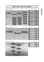
QUEBEC - TORONTO

DETROIT - BOSTON

63

71

126

27

22

10

4,5

G

OTTAWA - ATLANTA

E

D

63

81

126

17

13

7,5

9

12,5

10

18,5

11,5

F

H

A

B

C

27

22

10

4,5

G

E

D

17

13

7,5

9

12,5

10

18,5

11,5

F

H

A

B

C

8

MONTREAL - MIAMI

64,5

74

124

29,5

22

10

G

19,5

15,5

10

11

,5

15

10

18,5

11,5

F

H

B

E

D

A

C

4,5

=

refoulement eau chaude 3/4” M

sortie des fumées (Ø 10 cm)

C

retour eau 3/4” M

D

échappement vanne de sécurité 1/2” F

E

eau provenant du réseau 1/2” M

F

eau chaude sanitaire1/2” M

G

évacuation eau (latérale gche)

H

eau froide sanitaire provenant

de l'installation 1/2” M

N.B.:

si le kit de production ACS

interne n'est pas utilisé, les bouchons 

F et H présents sur les tuyaux ne 
doivent pas être retirés

=

refoulement eau chaude 3/4” M

sortie des fumées (Ø 10 cm)

C

retour eau 3/4” M

D

échappement vanne de sécurité 1/2” F

E

eau provenant du réseau 1/2” M

F

eau chaude sanitaire1/2” M

G

évacuation eau (latérale gche)

H

eau froide sanitaire provenant

de l'installation 1/2” M

N.B.:

si le kit de production ACS 

interne n'est pas utilisé, les bouchons 
F et H présents sur les tuyaux ne 
doivent pas être retirés

Summary of Contents for Atlanta

Page 1: ... MIAMI ATLANTA I Installazione uso e manutenzione p 2 UK Installation use and maintenance p 28 F Installation usage et maintenance p 54 E Instalación uso y mantenimiento p 80 D Installations Betriebs und Wartungsanleitung p 106 NL Installatie gebruik en onderhoud p 132 ...

Page 2: ...re senza intervenire Per un regolare funzionamento la termostufa deve essere installata rispettando quanto riportato su questa scheda Durante il funzionamento non deve essere aperta la porta la combustione è infatti gestita automaticamente e non necessita di alcun intervento In nessun caso devono essere introdotte nel focolare o nel serbatoio sostanze estranee Per la pulizia del condotto scarico f...

Page 3: ...4 5 74 124 29 5 22 10 G 19 5 15 5 10 11 5 15 10 18 5 11 5 A mandata acqua calda 3 4 M B uscita fumi Ø 10 cm C ritorno acqua 3 4 M D scarico valvola di sicurezza 1 2 F E acqua dalla rete 1 2 M F acqua calda sanitaria 1 2 M G scarico acqua laterale sx H acqua fredda dall impianto sanitario 1 2 M N B se il kit produzione ACS interno non è utilizzato non devono essere rimossi i tappi F e H presenti su...

Page 4: ...n accensione 400 W Frequenza radiocomando telecomando onderadio 2 4 GHz infrarossi Protezione su alimentazione generale Fusibile 2A 250 Vac 5x20 Protezione su scheda elettronica Fusibile 2A 250 Vac 5x20 FUSIBILE sulla presa con interruttore posta sul retro della termostufa sono inseriti due fusibili di cui uno funzionale e l altro di scorta PORTA SERIALE Sull uscita seriale RS232 con apposito cave...

Page 5: ...ema LEONARDO ottiene una combustione costante regolando automaticamente il tiraggio in base alle caratteristiche della canna fumaria curve lunghezza forma diametro ecc ed alle condizioni ambientali vento umidità pressione atmosferica installa zioni in alta quota ecc E necessario che siano rispettate le norme d installazione Il sistema LEONARDO è inoltre in grado di riconoscere il tipo di pellet e ...

Page 6: ...top è installato il pannello sinot tico L sul fronte per Montreal Miami Ottawa Atlanta che consente la gestione e la visualizzazione di tutte le fasi di funziona mento Le principali fasi possono essere gestite anche attraverso radiocomando Ottawa Atlanta e telecomando Quebec Toronto Montreal Detroit Boston Miami La termostufa è dotata sul retro di una presa seriale per collegamento con cavetto opt...

Page 7: ...ne dell acqua nella termostu fa Con termostufa funzionante la pressione consigliata è di 1 bar vedi pag 16 Microinterruttore rilevamento apertura portello solo per modello Boston Detroit Miami Atlanta Pressostato elettro idraulico solo per modello Boston Detroit Miami Atlanta IN CASO DI BLOCCO LA TERMOSTUFA NE SEGNALA IL MOTIVO A DISPLAY E MEMORIZZA L AVVENUTO BLOCCO Resistenza provoca l innesco d...

Page 8: ...riale infiammabile In caso di collegamento attraverso parete in legno o altro materiale infiammabile è necessario coibentare il tubo di scarico fumi con fibra ceramica o altro materiale di pari caratteristiche Presa d aria da realizzare inderogabilmente E necessario che il locale dove la termostufa è collocata abbia una presa di aria di sezione di almeno 80 cm2 tale da garantire il ripristi no del...

Page 9: ...rez za superiore a 35 F impiegare un addolcitore Per suggerimenti fare riferimento alla norma UNI 8065 1989 Trattamento dell acqua negli impianti termici ad uso civile Si riporta lo schema del kit idraulico incorporato nella termostufa per la produzione istantanea senza accumulo di ACS Circolatore OTTAWA è dotata di un circolatore con motore elettro nico di nuova generazione Valvola a 3 vie Valvol...

Page 10: ...a AF Acqua Fredda MI Mandata Impianto EV Elettrovalvola a 3 vie F Flussostato P Pompa circolatore Po Pompa OPTIONAL RE Regolatore elettronico RI Ritorno Impianto S Scarico Sc Scambiatore ST Sonda Temperatura V Valvola VE Vaso di espansione VR Valvola di ritegno VSP Valvola di sicurezza VST Valvola di scarico termico AF MI RI VR P Sc 30 V ACS V MI RI RA RA AF F AF EV MI RI VSP ACS VR ST P Sc RE Ret...

Page 11: ...mbiatore valvole ecc Per ogni informazione rivolgersi al rivenditore di zona 1 ACCENSIONE CAT Verificare che l impianto idraulico sia correttamente eseguito e sia dotato di vaso di espansione sufficiente a garantirne la sicu rezza La presenza del vaso incorporato nella termostufa NON garantisce adeguata protezione dalle dilatazioni termiche subite dal l acqua dell intero impianto Alimentare elettr...

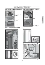
Page 12: ...ssare il frontalino in ceramica tramite le apposite staffe E e viti a testa esagonale in dotazione agendo sulla faccia posteriore del frontalino in ghisa N B se fosse necessario utilizzare la guarnizione in dotazione tra il frontalino in ceramica ed il frontalino in ghisa per compensare le possibili imprecisioni tipiche della ceramica Riposizionare il tutto incastrandolo nelle apposite mollette di...

Page 13: ...rontalino in ghisa fissaggio D D C E E MONTAGGIO RIVESTIMENTI vista del finito allontanare ceramica dal fianco avvicinare ceramica al fianco O Fase 4 montaggio fianchi in ceramica N H G O N I G cave M H 4 1 4 2 4 3 4 4 vite di regolazione fianchi fianco in ceramica lamiera zincata dentata accoppiamento profilo dentato cava retro fronte ITALIANO H H I I ...

Page 14: ...lamiera e spostare lievemente i 2 fianchi in alluminio B in avanti Infilare dall alto verso il basso i fianchi in ceramica C sulla parte interna dei fianchi in ceramica è segnata una freccia D che indica il lato della piastrella da orientare verso il fronte della stufa rispettare le viste dei fianchi E ed F Riposizionare i 2 fianchi in alluminio fissare i 4 perni precedendemente rimossi e posizion...

Page 15: ...ramica anta 2 387530 10 Bloccaggio ceramica frontale 2 388890 11 Vite T E 6x16 2 18650 12 Vite 4 2x6 5 2 235990 13 Distanziale 6 266670 pz cod 1 Frontalino inferiore rosso 1 642050 1 Frontalino inferiore panna 1 642040 2 Frontalino superiore rosso 1 642070 2 Frontalino superiore panna 1 642060 5 Top rosso 1 642130 5 Top panna 1 642120 6 Vite T B 6x12 2 284380 9 Bloccaggio ceramica anta 2 387530 10...

Page 16: ...azione Il CAT dovrà anche Verificare che l impianto idraulico sia correttamente eseguito e sia dotato di vaso di espansione sufficiente a garantirne la sicurezza La presenza del vaso incorporato nella termostufa NON garantisce adeguata protezione dalle dilatazioni termiche subite dal l acqua dell intero impianto Alimentare elettricamente la termostufa ed eseguire il collaudo a freddo da parte di C...

Page 17: ...iler o in generale del circuito secondario utilizzando i tasti Si puo visualizzare se collegato alla sonda boiler la temperatura di un eventuale boiler accumulo esterno premendo il tasto boiler si visualizza il set impostato premendo i tasti durante la visualizzazione del set boiler si varia detta impostazione Se la sonda boi ler non è collegata si visualizzano dei trattini al posto della temperat...

Page 18: ...1 a display compare Salvato Nel caso il pellet si esaurisca nel serbatoio la stufa va in blocco con la scritta Stop Fiamma Segnalazione riserva pellet Le termostufe sono dotate di funzione elettronica rilevamento di quantità pellet nel serbatoio Il sistema di rilevamento pellet integrato all interno della scheda elettronica permette di rilevare in qualsiasi momento durante il fun zionamento quanti...

Page 19: ...data Tm 65 C i Kg e l autonomia residua 50KG 10H e l ora corrente 15 33 Premendo il tasto A del radiocomando potremo commutare dalla classica modalità Modula_Potenze alla modalità Clima_Comfort In modalità Clima_Comfort premendo i tasti sul pannello sinottico oppure sul radiocomando si imposta la temperatura desi derata in ambiente avremo quindi ad esempio le seguenti situazioni Con temperatura am...

Page 20: ... di interventi ed a quali orari In caso di errore in qualunque momento della programmazione si può usci re dal programma senza salvare premendo tasto a display comparirà NO SALVATAGGIO Variazione alimentazione pellet SOLO A SEGUITO CONSIGLIO DEL CAT Premendo per due secondi il tasto M dal radiocomando e scorrendo le indicazioni del display con i tasti si incontra la descri zione ADJ PELLET Conferm...

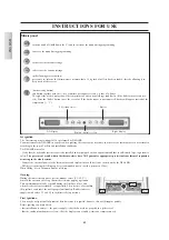
Page 21: ...consumati Pellt KG UTE 200 batteria scarica n 3 pile alkaline mini stilo AAA tastiera bloccata premere A e M in contemporanea per qual che secondo per bloccare o sbloccare la tastiera icona accesa termostufa in fase di accensione lavoro ISTRUZIONI D USO Indica una trasmissione di dati dal telecomando alla scheda Indica che si sta impostando un accensione spegnimento con il programma EASY TIMER Ind...

Page 22: ...emendo contempora neamente i tasti A e M si accenderà il simbolo della chiave a conferma del blocco tastiera avvenuto Per sbloccare la tastiera premere nuovamente i tasti A e M simultaneamente ISTRUZIONI D USO INFORMAZIONI AGLI UTENTI Ai sensi dell art 13 del decreto legislativo 25 luglio 2005 n 151 Attuazione delle Direttive 2002 95 CE 2002 96 CE e 2003 108 CE relative alla ridu zione dell uso di...

Page 23: ... messa in servizio il CAT imposta un valore di Kg di pellet consumati dopo il quale compare a display la scritta Manutenz_ione La termostufa continua il suo funzionamento ma il cliente finale deve conttatare il CAT per effettuare l indispensabile manutenzione stagionale Si invita il cliente finale indipendentemente dalla scritta che appare a display ad effettuare una manutenzione a stagione Prima ...

Page 24: ...24 ITALIANO MANUTENZIONE 2 fig A 3 1 fig B fig C fig D 4 3 4 3 2 4 fig E fig F fig G ...

Page 25: ...O Avvio Verificare posizionamento e pulizia del crogiolo funzionalità resistenza temperatura ambiente se inferiore 3 C serve accenditore es diavolina Chiedere intervento CAT per verifica funzionalità termocoppia temperatura di avvio impostata nei parametri POSSIBILI INCONVENIENTI 5 Mancata Energia spegnimento per mancanza energia elettrica non è un difetto della termostufa Verificare allacciamento...

Page 26: ... 8 Il crogiolo e il vano cenere sono puliti e ben posizionati E stato indicato di azionare ogni giorno le aste di pulizia I tubi di scambio e le parti interne al focolare sono puliti Il condotto fumi vedere pag 8 è pulito L impianto idraulico è stato sfiatato La pressione letta sul manometro è di circa 1bar CHECK LIST 13 FERMO G COCLEA 2 interviene quando il motoriduttore 2 è bloccato o guasto Ver...

Page 27: ... istantanea senza accumulo 6 Posso scaricare i fumi delle termostufe direttamente a parete NO lo scarico a regola d arte UNI 10683 05 deve raggiungere il colmo del tetto e comunque per il buon funzionamento è necessa rio un tratto verticale di almeno 1 5 metri ciò ad evitare che in caso di black out o di vento si formi una leggera quantità di fumo nel locale di installazione 7 E necessaria una pre...

Page 28: ... These are activated without any intervention required In order to function correctly the thermo stoves must be installed in accordance with the instructions given herein Whilst functioning the door must never be opened In fact combustion is fully automatic and requires no manual intervention Under no circumstances should any foreign substances be put into the hearth or the hopper Do not use flamm...

Page 29: ...REAL MIAMI 64 5 74 124 29 5 22 10 G 19 5 15 5 10 11 5 15 10 18 5 11 5 F H B E D A C 4 5 A hot water outlet 3 4 M B Smoke outlet Ø 10 cm C water return line 3 4 M D safety valve drainage 1 2 F E mains water 1 2 M F domestic hot water 1 2 M G water drainage left side H cold water from the plumbing system 1 2 M Note If the internal ACS produc tion kit is not utilized caps F and H on the pipes must no...

Page 30: ...R who has performed the first 1st ignition The data shown above is purely indicative EDILKAMIN reserves the right to make changes to these products to improve their performance with no prior warning SAFETY DEVICES FUSE two fuses are inserted in the soc ket with switch located on the back of the stove one of which operational and the other is held in reserve THERMOCOUPLE placed at the smoke outlet ...

Page 31: ...nditions wind humidity atmospheric pressure installations at high altitude etc The standards for installation must be respected LEONARDO system is also able to recognise the type of pellets and automatically adjust the flow moment by moment to ensure the required level of combustion use wood pellets with a diameter of approximately 6 mm Archimedes screw 2 probe ACS IN Panel control RPM smoke Water...

Page 32: ...lled on the top through which all phases of ope ration can be displayed and controlled The main phases can even be handled by radio control Ottawa Atlanta model and remote control Quebec Toronto Montreal Detroit Boston Miami models Aserial port is found at the back of the thermo stoves optio nal cable code 640560 to be connected to devices that allow remote ignition e g remote telephone local ther...

Page 33: ...ws you to read the water pressure in the ther mal thermo stoves With the thermal thermo stoves running the recommended pressure is 1bar see page 42 Microswitch door opening detection Boston Detroit Miami Atlanta Electro hydraulic pressure switch Boston Detroit Miami Atlanta IF THE THERMAL THERMO STOVES BLOCKS THE REASON WILLAPPEAR ON THE DISPLAYAND THIS WILL BE SAVED Resistance triggers pellet com...

Page 34: ...0 cm from the front Flammable objects must not be placed above the thermo stoves or at a distance that is any less than the stipulated safety distances If connected to wooden walls or other flammable materials the smoke exhaust pipe must be appropriately insulated with ceramic fibre or other similar material Air inlet to be mandatorily implemented The room where the thermo stoves is placed must ha...

Page 35: ...ter than 35 F use a water softener For suggestions please refer to regulation UNI 8065 1989 Water Treatment In Heating Systems For Civil Use The following is a schematic diagram of the hydraulic kit built into the stove for instant production without accumulation of ACS Circulator The Ottawa is equipped with a circulator with a new generation electronic motor 3 way valve Safety Valve Flow meter Pl...

Page 36: ... ACS Domestic Hot Water AF Cold Water MI System delivery EV 3 way Solenoid valve F Flow meter P Pump circulator Po Pump OPTIONAL RE Electronic Regulator RI System Return S Drainage Sc Exchanger ST Temperature Probe V Valve VE Expansion tank VR Check Valve VSP Safety valve VST Thermal discharge valve AF MI RI VR P Sc 30 V ACS V MI RI RA RA AF F AF EV MI RI VSP ACS VR ST P Sc RE Power V S VE AF ACS ...

Page 37: ...able exchanger valves etc For information please contact your local dealer 1 START UP DEALER Make sure the plumbing system has been properly executed and is equipped with an expansion tank which is sufficient to gua rantee safety The presence of the tank built in to the stove does NOT guarantee adequate protection from thermal expansion experienced by the water inside the system Power on the stove...

Page 38: ... panel using the brackets E and supplied hexagon head screws working from the back face of the cast iron front panel N B if necessary use the supplied trim between the ceramic front panel and the cast iron front panel in order to compensate for any in accuracies which are typical of ceramics Replace by fitting into the appropriate fastening clips Phase 4 Installation of ceramic side panels 4 2 App...

Page 39: ...ron front panel finished view fixing D D C E E MOUNTING THE COVERING finished view remove ceramic from the side panel Bring cera mic up to the side panel O Phase 4 mounting ceramic side panels O 4 1 4 3 I G Slot M H 4 2 4 4 side panel adjustment screw ceramic side panel toothed galvani zed sheet toothed profile coupling slot back front I I N H G N H H ...

Page 40: ...he 4 pins A from the plating top and move the 2 aluminium sides B slightly forward Put in the ceramic sides C in from the top downwards On the inside of the ceramic sides there is an arrow D that indicates the side of the tile that must be towards the front of the stove follow the views of the sides E and F Put the 2 aluminium sides back in position fix the 4 pins removed before and position the c...

Page 41: ...66940 9 Door ceramic blocking plate 2 387530 10 Front ceramic blocking plate 2 388890 11 Screw T E 6x16 2 18650 12 Screw 4 2x6 5 2 235990 13 Spacer 6 266670 pz cod 1 Red lower front panel 1 642050 1 Off white lower front panel 1 642040 2 Red upper front panel 1 642070 2 Off white lower front panel 1 642060 5 Red top 1 642130 5 Off white top 1 642120 6 Screw T B 6x12 2 284380 9 Door ceramic blockin...

Page 42: ... must also Verify that the hydraulic system is correctly installed and is equipped with an expansion tank that is sufficiently large to guarantee safety The presence of a tank within the thermo stoves does NOT guarantee appropriate protection from thermal expansion occurring in the whole system Connect the electrical power to the thermo stoves and implement a cold test to be carried out by the DEA...

Page 43: ...of the boiler or of the secondary circuit in general using the keys It is possible to visualise if the boiler probe is connected the temperature of any boiler external storage by pressing the boi ler key the set value is displayed by pressing the keys while viewing the boiler value set that setting can be varied If the boiler probe is not connected dashes appear in place of the temperature C Shutd...

Page 44: ...out saving by pressing the 0 1 key and Saved will appear on the display Should the hopper run out of pellets the stove will block and Stop Flame will appear Pellet reserve warning The thermal stoves are equipped with an electronic pellet detection system The pellet detection system is integrated into the electronic control board allowing the stove to monitor how many kilos of pellets are left This...

Page 45: ...control unit to switch from the classic Power_Module mode to Comfort_Climate mode In Comfort_Climate mode press the button on the radio control unit s synoptic panel to set the desired room temperature The following situations for example will occur With a room temperature below the setting the thermo stoves will modulate the power levels normally in order to pursue the output set If the room temp...

Page 46: ...M specific programme for each day individually Use the and keys to switch between programmes Use key M to confirm the option DAILY PROGRAM to choose the number of programmes turn on off to be carried out per day Use the DAILY PROGRAM to set identical programme s for every day of the week By then pressing the key the following can be seen Prog no 1st prog one turn on and one turn off per day 2nd pr...

Page 47: ...e EASY TIMER program M key for viewing setting the set temperature Set 70 C and the kg of consumed pellets Pellt KG UTE 200 Indicates data transmission between the remote con trol and the control board low batteries replace them and put them in their appropriate containers blocked keypad avoid turning on the remote control for no reason press A and M simultaneously for a few seconds to block unblo...

Page 48: ...d M buttons simultaneously and the key symbol will light up confirming that the keys have been blocked Press the A and M buttons simultaneously once again to unblock the keypad INSTRUCTIONS FOR USE INFORMATION FOR USERS In accordance with Art 13 of the Legislative Decree No 151 dated 25 July 2005 Implementation of Directives 2002 95 EC 2002 96 EC and 2003 108 EC pertaining to the reduction of haza...

Page 49: ...enance Seasonal cleaning implemented by the dealer The DEALER upon commissioning sets the kg value of consumed pellets after which the message Mainten will appear on the display The thermo stove continues operation but the end client must contact the DEALER to perform necessary seasonal maintenance The end client is invited to perform seasonal maintenance regardless of which messages may appear on...

Page 50: ...ENGLISH 50 MAINTENANCE 2 fig A 3 1 fig B fig C fig D 4 3 4 3 2 4 fig E fig F fig G ...

Page 51: ... a defect of the thermo stoves Check electricity connection and drops in voltage 6 Fault RC Shuts down due to a failure occurring in the thermocouple or it being disconnected Verify connection of thermocouple to the control board Verify functionality in a cold test 7 smoke C high Shuts down due to excessive smoke temperature An excessive smoke temperature may occur because of the following unsuita...

Page 52: ...e smoke channel chimney flue The smoke channel has a maximum of 2 curves a maximum of 2 horizontal metres at least 1 5 vertical metres The exhaust pipes are made of suitable material recommended stainless steel When using any flammable materials e g wood all precautions have been taken to prevent a fire hazard The heating capacity has been appropriately assessed considering radiator efficiency how...

Page 53: ... from the thermal stoves along the wall NO a discharge which is conform with standards UNI 10683 05 must reach the ridge of the roof and in any case proper functioning requires a vertical stroke of at least 1 5 meters avoiding that in case of power outage or wind a slight amount of smoke forms in the installation environment 7 Do I need an air inlet in the room where it is installed Yes to repleni...

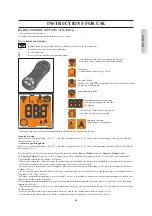
Page 54: ...rantissent l extinction qui doit se passer sans intervenir Pour un bon fonctionnement le thermopoêle doit être installé en respectant ce qui est indiqué sur cette fiche et pendant le fonction nement la porte ne doit pas être ouverte en effet la combustion est gérée automatiquement et ne nécessite aucune intervention En aucun cas des substances étrangères doivent être introduites dans le foyer ou d...

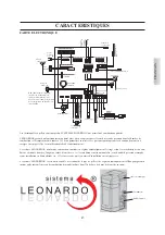
Page 55: ...G 19 5 15 5 10 11 5 15 10 18 5 11 5 F H B E D A C 4 5 A refoulement eau chaude 3 4 M B sortie des fumées Ø 10 cm C retour eau 3 4 M D échappement vanne de sécurité 1 2 F E eau provenant du réseau 1 2 M F eau chaude sanitaire1 2 M G évacuation eau latérale gche H eau froide sanitaire provenant de l installation 1 2 M N B si le kit de production ACS interne n est pas utilisé les bouchons F et H prés...

Page 56: ...e absorbée moyenne 120 W Puissance absorbée moyenne à l allumage 400 W Fréquence radiocommande télécommande ondes radio 2 4 GHz Infrarouges Protection sur alimentation générale Fusible 2A 250 Vac 5x20 Protection sur carte électronique Fusible 2A 250 Vac 5x20 FUSIBLE sur la prise avec interrupteur située à l arrière du poêle deux fusibles sont insères l un est fon ctionnel et l autre est de réserve...

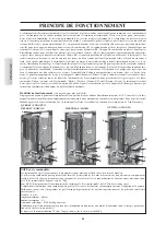
Page 57: ...e LEONARDO est en outre capable de reconnaitre le type de pellet et de régler automatiquement l afflux pour garantir instant après instant le niveau de combustion demandé utiliser du pellet de bois de 6 mm de diamètre environ carte electronique Vacuomètre Sonde fumées Li t hi um CR2032 Module radio tx sx OTTAWA Antenne Ottawa Atlanta Sonde de la vis sans fin 2 ACS IN Panneau commandes RPM fumées S...

Page 58: ...wa Atlanta est installé sur le haut et il per met de gérer et de visualiser toutes les phases de fonctionnement Les principales phases peuvent aussi être gérées grâce à la radio commande Ottawa Atlanta et la télécommande Quebec Toronto Montreal Detroit Boston Miami Le thermopoêle est doté d une prise sérielle à l arrière avec câble en option cod 640560 pour le raccordement avec des dispositifs d a...

Page 59: ...lanta il permet de lire la pression de l eau dans le thermo poêle Quand le thermopoêle fonctionne la pression conseillée est de 1 bars voir pag 68 Micro interrupteur de détection de l ouverture de la porte Boston Detroit Miami Atlanta Pressostat électro hydraulique Boston Detroit Miami Atlanta EN CAS DE BLOCAGE LE THERMOPOELE SIGNALE LE MOTIF SUR LE DISPLAY ET MEMORISE LE BLOCAGE QUI S EST PRODUIT...

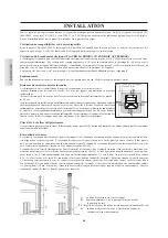
Page 60: ...horizontal admis peut avoir une longueur jusqu à 2 m En cas de liaison à travers des parois en bois ou autre matériau inflammable il faut calorifuger le conduit d évacuation des fumées avec de la fibre céramique ou un autre matériau avec les mêmes caractéristiques Prise d air à réaliser obligatoirement Il est nécessaire que la pièce où se trouve le thermopoêle ait une prise d air de section d au m...

Page 61: ...9 Traitement de l eau dans les installations thermiques à usage civil Nous indiquons le schéma du kit hydraulique intégré dans le thermopoêle pour la production instantanée sans accumulation d eau chau de sanitaire Circulateur L OTTAWA est équipée d un circulateur avec moteur électronique de nouvelle génération Soupape à 3 voies Vanne de sécurité Flussostat Échangeur à plaques LE CIRCULATEUR ELECT...

Page 62: ...e Sanitaire AF Eau Froide MI Refoulement Installation EV Électrovanne à 3 voies F Flussostat P Pompe circulateur Po Pompe OPTIONS RE Régulateur électronique RI Retour Installation S Évacuation Sc Échangeur ST Sonde Température V Soupape VE Vase d expansion VR Soupape antiretour VSP Soupape de sécurité VST Soupape d échappement thermique AF MI RI VR P Sc 30 V ACS V MI RI RA RA AF F AF EV MI RI VSP ...

Page 63: ...sont disponibles échangeur soupapes etc Pour toute information s adresser à son revendeur 1er ALLUMAGE REVENDEUR Vérifier que l installation hydraulique soit correctement effectuée et soit pourvue d un vase d expansion approprié pour garan tir la sécurité La présence du vase intégré dans le thermopoêle NE garantit pas de protection adéquate contre les dilatations thermiques subies par l eau de tou...

Page 64: ...dans les trous D situés sur l élément frontal en fonte C Fixer l élément frontal en céramique au moyen des étriers E et des vis à six pans fournies en agissant sur le côté postérieur de l élément frontal en fonte N B en cas de besoin appliquer le joint fourni entre l élément frontal en céramique et l élément frontal en fonte afin de compenser les éventuelles imprécisions typiques de la céramique R...

Page 65: ...arrière de l élément fron tal en fonte fixation D D C E E MONTAGE REVÊTEMENT Phase 4 montage des côtés en céramique 4 1 vue de l ensemble une fois monté O O 4 3 I G encoches M H 4 2 4 4 vis de réglage des côtés côté en céra mique tôle galvanisée dentée assemblage profil denté encoche derrière devant I I éloigner la céramique du côté approcher la cérami que du côté N H G N H H ...

Page 66: ...des céramiques Retirer les 4 chevilles A du haut en tôle et déplacer légèrement vers l avant les 2 flancs en aluminium B Enfiler du haut vers le bas les flancs en céramique C La partie interne des flancs en céramique présente une flèche D indiquant le côté du carreau à orienter vers la façade du poêle respecter les vues des flancs E et F Repositionner les 2 flancs en aluminium fixer les 4 cheville...

Page 67: ... 4 Petit coté crème 6 645750 5 Haut Rouge 1 642130 5 Haut créme 1 642120 6 Vis T b 6x12 12 284380 7 Plaques céramiques 10 647670 8 Vis 4 8x10 16 266940 9 Plaque blocage céramique volet 2 387530 10 Plaque blocage céramique frontale 2 388890 11 Vis T E 6x16 2 18650 12 Vis 4 2x6 5 2 235990 13 Entrotoise 6 266670 n code 1 Façade inférieure rouge 1 642050 1 Façade inférieure crème 1 642040 2 Façade sup...

Page 68: ...on Le REVENDEUR devra aussi Vérifier que l installation hydraulique est effectuée correctement et qu elle est dotée d un vase à expansion suffisant pour garantir la sécurité La présence du vase incorporé dans le thermopoêle NE garantit PAS une protection adaptée contre les dilatations thermiques subies par l eau de l installation toute entière Alimenter le thermopoêle en électricité et effectuer l...

Page 69: ...es On peut visualiser si le raccord à la sonde du chauffe eau a été effectué la température d un éventuel chauffe eau accumulation externe en appuyant sur la touche boiler on visualise les paramètres programmés et en appuyant sur les touches durant la visualisation des paramètres du chauffe eau on peut modifier cette programmation Si la sonde chauffe eau n est pas raccordée on visualise des tirets...

Page 70: ...ogramme sans sauver en appuyant sur la touche 0 1 sur le display apparait Sauvé Si le pellet s épuise dans le réservoir le poêle se bloque et affiche Stop Flamme Signalisation réserve pellet Les thermopoêles sont dotés d une fonction électronique de détection de quantité de pellet Le système de détection de pellet intégré à l intérieur de la carte électronique permet au poêle de contrôler à tout m...

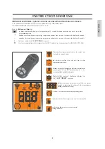
Page 71: ...ants 50KG 10H et l heure courante 15 33 En appuyant sur la touche A de la radiocommande on peut changer la modalité classique Moduler Puissances en modalité Climat_Confort En modalité Climat_Confort si on appuie sur les touches sur le panneau synoptique ou sur la radiocommande on règle la température souhaitée dans la pièce et on pourra donc avoir par exemple les situations suivantes Quand la temp...

Page 72: ...e M De la même manière pour le moment de l arrêt à programmer et pour les allumages successifs ou les arrêts O n confirme en appuyant sur M lorsque l inscription SAUVEGARDÉ apparaît à l écran En confirmant PROGRAM HEBDOMADAIRE on devra choisir le jour où l on veut effectuer la programmation 1 Lu 2 Ma 3 Me 4 Je 5 Ve 6 Sa 7 Di Après avoir sélectionné le jour en utilisant les touches et et en confirm...

Page 73: ...tion EASY TIMER M touche pour afficher régler la température Set 70 C et les Kg de pellets consommés Pellet KG UTE 200 Indique une transmission de données de la télécom mande à la carte Batterie déchargée la remplacer en ayant soin de la remettre dans son contenant spécial Clavier bloqué évite les mises en route non souhaitées appuyer sur A et M en même temps pendant quelques secondes pour bloquer...

Page 74: ...par un UTILISATION DU PROGRAMME EASY TIMER La nouvelle télécommande permet de gérer une nouvelle programmation horaire très intuitive et rapide à utiliser Si la thermopoêle est allumé on peut programmer une extinction à partir de la télécommande avec un différé pouvant aller de une à douze heures le temps restant avant l extinction programmée s affichera sur l écran du panneau synoptique Si la the...

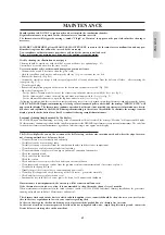
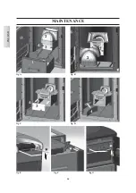
Page 75: ...evendeur règle une valeur de Kg de pellets consommés après laquelle l inscription Entret apparait sur l écran Le thermopoêle continue de fonctionner mais le client final doit contacter le Revendeur pour effectuer l indispensable entretien saisonnier Nous invitons le client final indépendamment de l inscription qui apparait sur l écran à effectuer un entretien par saison Avant d effectuer toute mai...

Page 76: ...76 FRANÇAIS ENTRETIEN 2 fig A 3 1 fig B fig C fig D 4 3 4 3 2 4 fig E fig F fig G ...

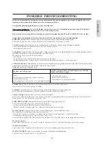
Page 77: ...branchements électriques et les baisses de tension 6 Panne télécom extinction pour cause de thermocouple en panne ou débranché Vérifier le branchement du thermocouple à la carte Vérifier le fonctionnement avec un test à froid 7 C fumées élevée extinction pour cause de dépassement température maximum des fumées Une température excessive des fumées peut dépendre de type de pellet non adapté anomalie...

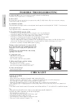
Page 78: ...niche cendres sont propres et bien positionnés Il a été indiqué d actionner chaque jour les tiges de nettoyage Les tuyaux d échange et les parties internes au foyer sont propres Le conduit de fumées voir page 60 est propre L installation hydraulique a été purgée La pression lue sur le manomètre est d environ 1bars CHECK LIST 13 STOP G VIS 2 intervient quand le motoréducteur 2 est boqué ou en panne...

Page 79: ...instan tanée sans accumulation 6 Est ce que je peux évacuer les fumées des thermopoêles directement au mur NON l évacuation effectuée dans les règles de l art UNI 10683 05 doit atteindre le sommet du toit et toutefois pour un bon fonction nement il est nécessaire d avoir un segment vertical d au moins 1 5 mètre cela pour éviter qu en cas de black out ou de vent se forme une légère fumée dans la pi...

Page 80: ...de seguridad que garantizan su apaga do que se dejará acontecer sin intervenir en ningún momento Para un funcionamiento regular la termoestufa ha de ser instalada respetando lo indicado en esta ficha y durante su funcionamiento la puerta no deberá abrirse de hecho la combustión es controlada automáticamente y no necesita ninguna intervención En ningún caso han de introducirse en el hogar o en el d...

Page 81: ... 5 74 124 29 5 22 10 G 19 5 15 5 10 11 5 15 10 18 5 11 5 F H B E D A C 4 5 A envío agua caliente 3 4 M G salida humos 10 cm Ø C retorno agua 3 4 M D descarga válvula de seguridad 1 2 F E agua de la red 1 2 M F agua caliente sanitaria 1 2 M G descarga agua lateral izq H agua fría de la instalación sanitaria 1 2 M N B si el kit de producción ACS interno no se utiliza no deben eliminarse los tapones ...

Page 82: ...ida 120 W Potencia absorbida media en el encendido 400 W Frecuencia del radio control mando a distancia ondas radioeléctricas 2 4 GHz infrarrojos Protección en alimentación general Fusible 2A 250 Vac 5x20 Protección en ficha electrónica Fusible 2A 250 Vac 5x20 FUSIBLE en la toma con interruptor coloca da detrás de la estufa hay introdu cidos dos fusibiles de los cuales uno funciona y el otro de re...

Page 83: ...en las normas de instalación Además el sistema LEONARDO puede reconocer el tipo de pellet y regular automáticamente el aflujo para garantizar a cada momento el nivel de combustión solicitado utilizar pellet de leña de unos 6 mm de diámetro ficha electronica Vacuómetro Sonda humos Li t hi um CR2032 Módulo radio tx sx OTTAWA Antena Ottawa Atlanta Sonda cóclea 2 ACS IN Cuadro de mandos RPM humos Sond...

Page 84: ...á instalado el panel sinóptico L y en la parte frontal para Montreal Miami Ottawa Atlanta que permite la gestión y la visualización de todas las fases de funcionamiento Las principales fases pueden ser gestionadas también a través de radio control Ottawa Atlanta y mando a distancia Quebec Toronto Montreal Detroit Boston Miami La termoestufa está equipada en la parte posterior con una toma de serie...

Page 85: ...elo Ottawa Atlanta permite leer la presión del agua en la termoe stufa Con la termoestufa en funcionamiento la presión aconsejada es de 1 1 5 bar ver pág 94 Microinterruptor de detección apertura portillo Boston Detroit Miami Atlanta Presostato electro hidráulico Boston Detroit Miami Atlanta EN CASO DE BLOQUEO LATERMOESTUFASEÑALAELMOTIVO EN LAPANTALLAYMEMORIZAELBLOQUEO EFECTUADO Resistencia provoc...

Page 86: ... colocados objetos de material inflamable En caso de conexión con pared de madera u otro material inflamable es necesario aislar el tubo de descarga de humos con fibra cerámica u otro material de similares características Toma de aire que realizar necesariamente Es necesario que el local donde la termoestufa está colocada tenga una toma de aire de sección de al menos 80 cm que garantice el resta b...

Page 87: ...norma UNI 8065 1989 Tratamiento del agua en las insta laciones térmicas de uso civil Se hace referencia al esquema del kit hidráulico incorporado en la termoestufa para la producción instantánea sin acumulación de ACS Circulador La caldera OTTAWA está dotada de un circulador con motor electrónico de nueva generación Válvula de 3 vías Válvula de seguridad Flujostato Intercambiad or de placas EL CIR...

Page 88: ...a sanitaria AF Agua fría MI Envío Instalación EV Electroválvula de 3 vías F Flujostato P Bomba circulador Po Bomba OPCIONAL RE Regulador electrónico RI Retorno instalación S Descarga SC Cambiador ST Sonda Temperatura V Válvula VE Vaso de expansión VR Válvula de retención VSP Válvula de seguridad VST Válvula de descarga térmica AF MI RI VR P Sc 30 V ACS V MI RI RA RA AF F AF EV MI RI VSP ACS VR ST ...

Page 89: ...biador válvulas etc Para cualquier información contactar al vendedor de zona 1 ENCENDIDO VENDEDOR Comprobar que el sistema hidráulico haya sido realizado correctamente y esté dotado de vaso de expansión suficiente para garantizar su seguridad La presencia del vaso incorporado en la termoestufa NO garantiza una adecuada protección de las dilataciones térmicas sufri das por el agua de toda la instal...

Page 90: ...e frontal de cerámica por medio de las abrazaderas correspondientes E y los tornillos con cabeza hexagonal entregados con el equipo trabajando en la cara posterior de la parte frontal de fundición N B si fuera necesario utilizar la empaquetadura suministrada entre la parte frontal de cerámica y la de fundición para compensar las posibles imprecisiones típicas de la cerámica Volver a colocar todo e...

Page 91: ...ior de la parte frontal de fundición fijación D D C E E MONTAJE REVESTIMIENTO vista del trabajo terminado Fase 4 montaje lados de cerámica 4 1 O O 4 3 I G Ranuras M H 4 2 4 4 tornillo de regulación lados lado de cerá mica chapa galvaniza da dentada acoplamiento perfil dentado ranura parte trasera frente I I Alejar cerámica del lado Acercar cerámica del lado N H G N H H ...

Page 92: ...os A de la encimera de chapa y desplazar ligeramente hacia adelante los 2 laterales de aluminio B Insertar de arriba hacia abajo los laterales de cerámica C en la parte interna de los laterales de cerámica está marcada una flecha D que indica el lado del azulejo a orientar hacia el frontal de la estufa respetar las vistas de los laterales E y F Poner de nuevo los 2 laterales de aluminio fijar los ...

Page 93: ... 5 Parte superior roja 1 642130 5 Parte superior nata 1 642120 6 Tornillo T b 6x12 12 284380 7 Placas cerámicas 10 647670 8 Tornillo 4 8x10 16 266940 9 Placa de bloqueo cerámica puerta 2 387530 10 Placa de bloqueo cerámica frontal 2 388890 11 Tornillo T E 6x16 2 18650 12 Tornillo 4 2x6 5 2 235990 13 Distanciador 6 266670 n cód 1 Parte frontal inferior roja 1 642050 1 Parte frontal inferior nata 1 ...

Page 94: ...la termoestufa NO garantiza una adecuada protección de las dilataciones térmicas sufridas por el agua de toda la instalación La presencia del vaso incorporado en la termoestufa NO garantiza una adecuada protección de las dilataciones térmicas sufridas por el agua de toda la instalación Alimentar eléctricamente la termoestufa y efectuar el ensayo en frío por parte del Vendedor Realizar el rellenado...

Page 95: ...secundario utilizando las teclas Se puede visualizar al unir la sonda caldera la temperatura de una posible caldera acumulador externo presionando la tecla caldera se visualiza el set programado presionando las teclas durante la visualización del set caldera varía dicha programación Si no se une la sonda caldera se visualizan guiones en lugar de la temperatura C Apagado Con la estufa funcionando a...

Page 96: ... tecla 0 1 en la pan talla aparece Guardado Si le pellet s épuise dans le réservoir le poêle se bloque et affiche Stop Llama Señalización reserva pellet Las termoestufas están dotadas de función electrónica de detección de cantidad pellet El sistema de detección pellet integrado den tro de la ficha electrónica permite monitorizar en cualquier momento durante el funcionamiento cuántos kg faltan par...

Page 97: ...de envío Tm 65 C los Kg y la autonomía residual 50KG 10H y la hora corriente 15 33 Pulsando la tecla A del mando a distancia podremos conmutar de la clásica modalidad Modulac _Potenci a la modalidad Clima_Confort En modalidad Clima_Confort pulsando las teclas en el panel sinóptico o en el radio control se programa la temperatura deseada en ambiente por lo tanto tendremos por ejemplo las siguientes...

Page 98: ...la tecla M Análogamente para el momento del apagado que programar y para los sucesivos encendidos o apagados se confirma presionando M al aparecer la anotación GRAVAR en la pantalla Confirmando PROGRAMA SEMANAL se deberá elegir el día en el cual efectuar la programación 1 Lu 2 Mar 3 Miér 4 Jue 5 Vier 6 Sáb 7 Dom Una vez seleccionado el día utilizando las teclas y y confirmando con la tecla M se pr...

Page 99: ...ASY TIMER M tecla para visualizar programar el set de temperatura Set 70 C y los Kg de pellet consumidos Pellt KG UTE 200 Indica una transmisión de datos del mando a distan cia a la tarjeta batería descargada sustituirlas eliminándolas en los contenedores apropiados teclado bloqueado evita activaciones no deseadas pulsar A y M al mismo tiempo durante algunos segundos para bloquear desbloquear el t...

Page 100: ...nuevo mando a distancia permite controlar una nueva programación horaria muy intuitiva y rápida que se usará Si el termo estufa está encendido se puede programar desde el mando a distancia un apagado con un reenvío regulable entre una y doce horas en la pantalla del panel sinóptico se visualizará el tiempo que falta para el apagado programado Si el termo estufa está apagado se puede programar desd...

Page 101: ...l Vendedor programa un valor de Kg de pellet consumidos después del cual aparece en la pantalla la anotación Manten La termoestufa sigue funcionando pero el cliente final deberá contactar con el Vendedor para efectuar el manteni miento indispensable de temporada El cliente final independientemente de la anotación que aparece en la pantalla deberá efectuar un mante nimiento de temporada Antes de re...

Page 102: ...102 ESPAÑOL MANUTENCIÓN 2 fig A 3 1 fig B fig C fig D 4 3 4 3 2 4 fig E fig F fig G ...

Page 103: ...omprobar conexión eléctrica y bajadas de tensión 6 Avería TC apagado por termopar averiado o desconectado Comprobar conexión de la termocupla a la ficha Comprobar funcionalidad en el ensayo en frío 7 C humos alta apagado por superación temperatura máxima humos Una temperatura excesiva de los humos puede depender de tipo de pellet anomalía extracción de humos canal de humos obstruido instalación no...

Page 104: ... es húmedo humedad máxima admitida 8 El crisol y el espacio cenizas están limpios y bien colocados Se recomienda accionar todos los días las varillas de limpieza Los tubos de intercambio y las partes internas del hogar están limpias El conducto de humos ver página 86 está limpio La instalación hidráulica se ha vaciado La presión leída en el manómetro es de aprox 1 bar LISTA DE COMPROBACIÓN 13 STOP...

Page 105: ...ran también agua caliente sanitaria Se puede producir agua caliente sanitaria utilizando el KIT incorporado en la termoestufa se trata de una producción instantánea sin acumulación 6 Puedo descargar los humos de las termoestufas directamente en pared NO la descarga a norma de ley UNI 10683 05 está en el tope del techo y en todo caso para el buen funcionamiento es necesario un tramo vertical de al ...

Page 106: ...die deren Abschalten gewährleisten dieses muss ohne Eingreifen des Benutzers automatisch erfolgen Für einen ordnungsgemäßen Betrieb muss der Einsatz unter Einhaltung der in diesem technischen Merkblatt enthaltenenAngaben installiert wer den Während des Betriebs darf die Tür nicht geöffnet werden Die Verbrennung wird nämlich automatisch verwaltet und bedarf keines Eingriffs In keinem Fall dürfen in...

Page 107: ...satz nicht verwendet wird dürfen F und H auf den Rohren nicht entfernt werden A Warmwasser Vorlauf 3 4 M B Rauch Abzug Ø 10 cm C Warmwasser Rücklauf 3 4 M D Auslauf Sicherheitsventil 1 2 F E Wasser vom Netz 1 2 M F Warmwasser 1 2 M G Wasser Auslauf seitlich rechts H Kaltwasser vom Brauchwasserkreis 1 2 M N B Wenn der interne Warmbrauchwasser Bausatz nicht verwendet wird dürfen F und H auf den Rohr...

Page 108: ...stungsaufnahme 120 W Leistungsaufnahme bei Zündvorgang 400 W Frequenz der Funkbedienung Fernbedienung Funkwelle 2 4 Hz Infrarotwellen Schutzvorrichtung auf Hauptversorgung Sicherung 2A 250 VWS 5x20 Schutzvorrichtung auf elektronischer Schaltkarte Sicherung 2A 250 VWS 5x20 SICHERUNG am Stromanschluss mit Schalter auf der Rückseite des Ofens sind zwei Sicherungen eingesetzt davon einer funktionsfähi...

Page 109: ...e den Pellet Typ zu erkennen und dessen Beschickung automatisch zu regeln um in jedemAugenblick das Maß der erforderlichen Verbrennung zu gewährleisten Holz Pellet von einem Durchmesser von etwa 6 mm verwenden elektronische schaltkarte Unterdruckmesser Rauchgas Sonde Li t hi um CR2032 Funk Sende Empfangsteil tx sx OTTAWA Antenne Ottawa Atlanta Sonde Förderschnecke 2 ACS IN Bedientafel RPM Umdrehun...

Page 110: ...r Montreal Miami Ottawa Atlanta auf der Vorderseite eingebaut das den Betrieb und die Anzeige aller Betriebsphasen ermöglicht Die Hauptbedienschritte können auch mithilfe der Funkbedienung Ottawa Atlanta oder der Fernbedienung Quebec Toronto Montreal Detroit Boston Miami erfolgen Der Pellet Heizöfen ist auf der Rückseite mit einem seriellen Anschluss für die Verbindung mittels des auf Wunsch erhäl...

Page 111: ...ofen Bei Ofen in Betrieb wird ein Druck von 1 bar empfohlen siehe Seite 120 Mikroschalter Erfassung Öffnung der Tür Boston Detroit Miami Atlanta Elektrisch hydraulischer Druckwächter Boston Detroit Miami Atlanta IM FALL EINER BLOCKIERUNG ZEIGT DER HEIZOFEN DIE URSACHE AUF DEM DISPLAY AN UND SPEICHERT DIE ERFOLGTE BLOCKIERUNG Widerstand Verursacht das Auslösen der Verbrennung des Pellet Er bleibt e...

Page 112: ...ch eine Wand aus Holz oder anderem brennbaren Material muss das Rauchabzugsrohr angemessen mittels Keramikfaser oder anderem Material mit gleichen Eigenschaften gedämmt werden Lufteinlass unbedingt zu verwirklichen Der Raum muss eine Frischluftöffnung von 200 cm nach außen haben oder gleichwertig per Luftverbund zur Verfügung stehen Es darf nur einen Heizöfen am Luftverbund angeschlossen werden Ra...

Page 113: ...ür Tipps auf die Norm UNI 8065 1989 Wasseraufbereitung in Haushalts Heizungsanlagen beziehen Es wird das Schaltbild des Hydraulik Bausatzes abgebildet das im Heizofen für die Durchlauferhitzung des Brauchwassers eingebaut ist Umwälzpumper OTTAWA ist mit einer Umwälzpumpe mit Elektronik Motor neuer Generation ausgestattet Dreiwegeventil Sicherheitsventil Flussmesser Platten Wärmetauscher DIE ELEKTR...

Page 114: ...auchwasser AF Kaltwasser MI Anlagen Vorlauf EV Dreiwege Elektroventil F Flussmesser P Umwälz Pumpe Po Pumpe OPTIONALES RE Elektronischer Regler RI Anlagen Rücklauf S Ablauf Sc Wärmetauscher ST Temperatur Sonde V Ventil VE Ausdehnungsgefäß VR Rückschlagventil VSP Sicherheitsventil VST Überhitzungsschutzventil AF MI RI VR P Sc 30 V ACS V MI RI RA RA AF F AF EV MI RI VSP ACS VR ST P Sc RE NETZ V S VE...

Page 115: ...Wenden Sie sich zwecks Auskünften an Ihren Händler 1 INBETRIEBNAHME Händler Überprüfen dass die Leitungsanlage ordnungsgemäß ausgeführt wurde und mit einem für die Gewährleistung der Sicherheit ausreichenden Ausdehnungsgefäß versehen ist Das Vorliegen des im Heizofen eingebauten Ausdehnungsgefäßes gewährleistet NICHT einen ausreichenden Schutz vor den Volumenausdehnungen des Wassers der gesamten A...

Page 116: ...Bügel E und mitgelieferten Sechskantkopf Schrauben von der Rückseite der Gusseisenblende aus befestigen NB Falls erforderlich die mitgelieferte Dichtung zwischen der Keramikblende und der Gusseisenblende verwenden um etwaige mögliche Ungenauigkeiten die für Keramik typisch sind auszugleichen Das Ganze wieder in die entsprechenden Halterungsfedern eindrücken Phase 4 Montage der Keramik Seitenteile ...

Page 117: ...stigung D D C E E MONTAGE DER VERKLEIDUNG Phase 4 Montage der Keramik Seitenteile Fertige Ansicht Fertige Ansicht 4 1 O O 4 3 I G Einschnitte M H 4 2 4 4 Seiten Einstell Schraube Keramik Seite Gezähntes Zinkblech Passung gezähntes Profil Einschnitt Rückseite Vorderseite I I Keramik vom Seitenteil Entfernen Keramik an das Seitenteil annähern N H G N H H ...

Page 118: ...A aus dem Blech Top herausnehmen und die 2 Seitenteile B aus Aluminium leicht nach vorn verschieben Die Seitenteile aus Keramik C von oben nach unten einschieben auf der Innenseite der Keramikseitenteile befindet sich ein Pfeil D der die Fliesenseite angibt die zur Ofenvorderseite zeigen soll die Ansicht der Seitenteile E und F einhalten Die 2 Seitenteile aus Aluminium wieder in Position bringen d...

Page 119: ...50 5 Oberteil rot 1 642130 5 Oberteil sahne 1 642120 6 Schraube T b 6x12 12 284380 7 Keramikplättchen 10 647670 8 Schraube 4 8x10 16 266940 9 Befestigungsplättchen Tür Keramik 2 387530 10 Befestigungsplättchen vordere Keramik 2 388890 11 Schraube T E 6x16 2 18650 12 Schraube 4 2x6 5 2 235990 13 Abstandshalter 6 266670 n Art Nr 1 Untere Blende rot 1 642050 1 Untere Blende sahnefarben 1 642040 2 Obe...

Page 120: ...s ebenfalls Das Vorliegen des im Heizofen eingebauten Ausdehnungsgefäßes gewährleistet nicht den angemessenen Schutz vor den thermischen Ausdehnungen des Wassers der gesamten Anlage Das Vorliegen des im Heizofen eingebauten Ausdehnungsgefäßes gewährleistet KEINEN ausreichenden Schutz vor den Wärmeausdehnungen des Wassers der gesamten Anlage Den Ofen mit Strom versorgen und die Abnahme im kalten Zu...

Page 121: ...lertemperatur oder allgemein des Nebenkreises durch Verwendung der Tasten verändert werden Es kann die Temperatur eines etwaigen externen Boilers Speichers falls mit der Boiler Sonde verbun den angezeigt werden durch Drücken der Taste Boiler wird die eingegebene Einstellung angezeigt durch Drücken der Tasten während der Anzeige der Boilereinstellung wird diese Einstellung verändert Ist die Boiler ...

Page 122: ...hriftzug Gespeichert Versiegt das Pellet im Behälter blockiert der Ofen und es wird der Schriftzug FlamAus NoPellet angezeigt Pelletreserve Anzeige Die Pellet Heizöfen QUEBEC TORONTO OTTAWA sind mit einer elektronischen Funktion zur Messung der Pelletmenge verse hen Die Messvorrichtung die im Inneren der elektronischen Schaltkarte integriert ist ermöglicht dem Ofen jederzeit zu überwachen wie viel...

Page 123: ...e und Autonomie 50KG 10H und die aktuelle Uhrzeit 15 33 Durch Drücken der Taste A der Fernbedienung kann man von der klassischen Modalität Leistung_sabstim zur Modalität Klima_Komfort wechseln Durch Drücken der Tasten auf dem Bedienfeld oder auf der Fernbedienung in der Modalität Klima_Komfort wird die gewün schte Raumtemperatur eingestellt man erhält daher zum Beispiel folgende Situationen Bei ei...

Page 124: ...der Taste M Auf dem Display erscheint 1 EIN 30 Uhr mit der Taste und verändert man die Minuten und bestätigt mit der Taste M Gleiches Vorgehen für den Zeitpunkt des Abschaltens und für die folgenden Ein und Abschaltungen Mittels der Taste M bestätigt man bei Anzeige des Schriftzuges SPEICHERN auf dem Display Bestätigt man WOCHENPROGRAMM ist der Tag zu wählen an dem die Programmierung vorgenommen w...

Page 125: ...eln M Taste für die Anzeige bzw Einstellung der Temperatur Set 70 C und die verbrauchte Pellet Menge in kg Pellt KG UTE 200 Zeigt eine Datenübertragung von der Fernbedienung zur Karte an Batterien verbraucht beim Austausch darauf achten sie in die entsprechenden Fächer einzusetzen Tastatur gesperrt um unerwünschte Schaltungen zu verhindern A und M gleichzeitig einige Sekunden lang drücken um die T...

Page 126: ...glicht eine sehr intuitive und schnell vorzunehmende Zeitplanung Ist der Pellet Heizöfen eingeschaltet Es ist möglich mit der Fernbedienung ein Abschalten mit einer zwischen einer und zwölf Stunden regelbaren Einstellung vorzunehmen im Display des Bedienfeldes wird die bis zur programmierten Abschaltung verbliebene Zeit angezeigt Ist der Pellet Heizöfen ausgeschaltet Es ist möglich mit der Fernbed...

Page 127: ...drücken Saison Reinigung seitens des Händlers Während der Inbetriebnahme stellt der Händler einen Wert in kg für die verbrauchte Pelletmenge ein nachdem auf dem Display der Schriftzug Reini grunKunde erscheint Der Heizofen setzt seinen Betrieb fort der Endkunde ist jedoch gehalten den Händler zu benachrichtigen um die unerlässliche jahreszeitliche Wartung vornehmen zu lassen Der Endkunde wird ange...

Page 128: ...128 DEUTSCH WARTUNG 2 Abb A 3 1 Abb B Abb C Abb D 4 3 4 3 2 4 Abb E Abb F Abb G ...

Page 129: ...wankungen überprüfen 6 FBdefekt Funkstö Abschalten wegen defekten oder nicht angeschlossenen Thermoelements Den Anschluss des Thermoelements an die Schaltkarte überprüfen Dessen Betrieb bei Abnahme in kaltem Zustand überprüfen 7 zu hohe Abgast Abschalten wegen zu hoher Rauchgastemperatur Ein zu hohe Rauchgastemperatur kann abhängen von Pellettyp Störung des Rauchabzugs verstopfter Rauchkanal nicht...

Page 130: ... von guter Qualität und nicht feucht max zulässige Feuchtigkeit 8 Die Reinigungsstangen werden täglich betätigt Die Wärmetauscherrohre und das Innere des Brennraums sind sauber Der Rauchabzug siehe Seite 112 ist sauber Die Hydraulikanlage wurde entlüftet Der auf dem Manometer abgelesene Druck beträgt etwa 1 bar CHECK LIST 13 STOP G SCHNEC 2 greift ein wenn der Getriebemotor 2 blockiert oder defekt...

Page 131: ...st möglich Warm Brauchwasser mithilfe des im Heizofen eingebauten Bausatzes zu erzeugen Es handelt sich um eine Durchlauferhitzung ohne Speicherung 6 Kann ich die Rauchgase der Heizöfen direkt aus der Wand ablassen NEIN der ordnungsgemäß UNI 10683 05 ausgeführte Abzug muss den Dachfirst erreichen und jedenfalls ist für einen einwandfre ien Betrieb ein senkrechtes Stück von mindestens 1 5 Metern er...

Page 132: ...thermokachel geïnstalleerd worden in overeenstemming met de aanwijzingen van dit blad Voorkom de opening van de deur tijdens de functionering de verbranding wordt automatisch aangestuurd Ingrepen zijn dus niet noodzakelijk Voorkom het invoeren van vreemde voorwerpen in de vuurhaard of in de tank Voorkom het gebruik van ontvlambare producten voor de reiniging van het rookkanaal Maak voor de reinigi...

Page 133: ...roductiekit Warm Water voor Sanitair Gebruik niet gebruikt wordt A toevoer warm water 3 4 M B rookafvoer Ø 10 cm C terugvoer water 3 4 M D afvoer veiligheidsklep 1 2 F E water afkomstig van waternet 1 2 M F warm water voor sanitair gebruik 1 2 M G waterafvoer zijkant l H koud water afkomstig van sanitaire installatie 1 2 M N B verwijder de doppen F en H op de leidingen nooit als de productiekit Wa...

Page 134: ... ELEKTRISCHE EIGENSCHAPPEN Voeding 230Vac 10 50 Hz Schakelaar on off ja Gemiddeld geabsorbeerd vermogen 120 W Geabsorbeerd vermogen tijdens ontsteking 400 W Frequentie radiobediening afstandsbediening radiogolven 2 4 GHz infrarood Beveiliging op hoofdvoeding Zekering 2A 250 Vac 5x20 Beveiliging op elektronische kaart Zekering 2A 250 Vac 5x20 ZEKERING op het contact met schakelaar aan de achterkant...

Page 135: ...LEONARDO systeem is tevens in staat het soort pellet te herkennen en automatisch de toevoer ervan af te stellen zodat keer op keer het vereiste verbrandingsniveau gegarandeerd wordt maak gebruik van houtpellets met een doorsnede van ongeveer 6 mm elektronische kaart Vacuümmeter Rookmeter Li t hi um CR2032 Module radio tx sx OTTAWA Antenne Ottawa Atlanta Meter toevo erschroef 2 ACS IN Bedieningspan...

Page 136: ... de besturing en de weergave van de verschillende functioneringsfases mogelijk maakt De hoofdzakelijke fasen kunnen ook bestuurd worden via radiobediening Ottawa Atlanta en afstandsbediening Quebec Toronto Montreal Detroit Boston Miami De kachel is aan de achterkant voorzien van een serieel contact voor de aanslui ting op remote inschakelapparatuur met behulp van het optionele kabeltje code 640560...

Page 137: ...edt u de mogelijkheid de water druk in de thermokachel af te lezen De aanbevolen druk bij functionerende thermokachel is 1 1 5 bar zie pag 146 Microschakelaar detectie openen deur Boston Detroit Miami Atlanta Elektrisch hydraulische drukregelaar Boston Detroit Miami Atlanta IN HET GEVAL VAN EEN BLOKKERING SIGNALEERT DE THERMOKACHEL OP HET DISPLAY DE OORZAAK HIERVAN DE BLOKKERING WORDT VERVOLGENS O...

Page 138: ...iner zijn dan de veiligheidsafstanden mogen geen voorwerpen van ontvlambare materialen worden geplaatst In het geval van een aansluiting op een houten wand of een wand van andere ontvlambare materialen is het noodzakelijk de rookafvoerleiding met keramiekfiber of een materiaal met soortgelijke eigenschappen te isoleren Luchttoevoer absoluut noodzakelijk Het is noodzakelijk dat de installatieruimte...

Page 139: ... 35 F Voor tips raadpleeg de normen UNI 8065 1989 Behandeling van water in openbare verwarmingsinstallaties Hieronder geven we het schema van de hydraulische kit voor de onmiddellijke productie zonder ophoping van Warm Water voor Sanitair Gebruik die in de thermokachel ingebouwd is Pomp OTTAWA is uitgerust met een pomp met elektronische motor van de nieuwe generatie 3 wegs klep Veiligheidsklep Deb...

Page 140: ...DA ACS Warm Water voor Sanitair Gebruik AF Koud Water MI Toevoer Installatie EV 3 wegs elektroklep F Debietregelaar P Pomp circulator Po Pomp OPTIONELE RE Elektronische regelaar RI Terugvoer Installatie S Afvoer Sc Warmteuitwisselaar ST Temperatuurmeter V Klep VE Expansievat VR Terugslagklep VSP Veiligheidsklep VST Thermische afvoerklep AF MI RI VR P Sc 30 V ACS V MI RI RA RA AF F AF EV MI RI VSP ...

Page 141: ...e waarborgen De aanwezigheid van het ingebouwde expansievast biedt GEEN voldoende garantie tegen de thermische uitzettingen van het water in de hele installatie Voorzie de thermokachel van stroom en keur hem zolang hij koud is Vul de installatie met behulp van het toevoerkraantje we raden u aan om een druk van ongeveer 1 bar te waarborgen Laat tijdens de vulfase de pomp ontluchten en open de handm...

Page 142: ... de speciale beugels E en bijgeleverde zeskantschroeven aan de achterkant van het gietijzeren voorpaneel N B maak indien noodzakelijk gebruik van de bijgesloten pakking en breng deze aan tussen de keramieken voortegel en het gietijzeren voorelement om de eventuele oneffenheden van de keramiektegels te compenseren Hermonteer het voorpaneel door hem op de speciale veren aan te brengen Fase 4 De kera...

Page 143: ...jzeren voorpaneel bevestiging D D C E E MONTAGE BEKLEDING Fase 4 montage keramieken zijtegels aanzicht complete kachel 4 1 O O 4 3 I G holtes M H 4 2 4 4 stelschroe ven zijtegels keramieken zijtegel verzinkte plaat met tanden koppeling profiel holte met tanden achterkant voorkant I I Verwijder de keramiek zijtegel van de zijkant Breng de keramieken zijtegel naar de zijkant toe N H G N H H ...

Page 144: ...en top en verplaats lichtjes de 2 zijkanten in aluminium B naar voren Van boven naar onderen de keramische zijkanten C inbrengen aan de binnenkant van de keramische zijkanten is een pijl aange bracht D die de kant van de tegels aantoont die naar de voorkant van de kachel moeten worden georiënteerd respecteer het zicht van de zijkanten E en F De zijkanten in aluminium opnieuw op hun plaats brengen ...

Page 145: ...laatje keramiektegels voor 2 388890 11 Schroef T E 6x16 2 18650 12 Schroef 4 2x6 5 2 235990 13 Afstandshouders 6 266670 n code 1 Voorelement onder rood 1 642050 1 Voorelement onder roomwit 1 642040 2 Voorelement boven rood 1 642070 2 Voorelement boven roomwit 1 642060 5 Bovenstuk rood 1 642130 5 Bovenstuk roomwit 1 642120 6 Schroef T B 6x12 2 284380 9 Vergrendelplaatje keramiektegels deur 2 387530...

Page 146: ...ulische installatie op correcte wijze uitgevoerd is en dat de installatie voorzien is van een expansievat dat groot genoeg is om de veilige functionering te kunnen garanderen De aanwezigheid van een expansievast dat in de thermokachel ingebouwd is vormt GEEN passende bescherming tegen de thermische uitzettingen van het water in de installatie Voorzie de thermokachel van een elektrische voeding en ...

Page 147: ...ter van de boiler aangesloten is Met een druk op de toets boiler wordt de ingestelde waarde weergegeven U kunt deze instelling van de boiler tijdens de weergave wijzigen met behulp van de toetsen In plaats van de temperatuur worden streepjes weergegeven C als de meter van de boiler niet aangesloten is Uitdoving Druk 2 lang op de toets 0 1 als de kachel functioneert De uitdoving wordt opgestart en ...

Page 148: ...rammering het programma verlaten zonder dat u de gege vens opslaat Druk hiervoor op de toets 0 1waarna op het display het bericht Saved weergegeven wordt In het geval dat de pellets in de tank opraken wordt de thermokachel geblokkeerd en wordt het bericht Stop Flame weergegeven Reservesignalering pellets De thermokachels zijn voorzien van een elektronische functie voor het opmeten van de hoeveelhe...

Page 149: ... 10 H en het tijdstip 15 33 worden weergegeven Met een druk op de toets A van de radiobediening kunt u van de normale modaliteit Power_Module overschakelen naar de modaliteit Comfort_Climate In de modaliteit Comfort_Climate kunt u met een druk op de toetsen van het synoptische paneel of de radiobediening de gewenste kamertemperatuur instellen De volgende situaties kunnen zich bijvoorbeeld voordoen...

Page 150: ... toets M wordt bevestigd Op de display verschijnt 1 ON minuten 30 met de toets en worden de minuten gewijzigd en met de toets M wordt bevestigd Voor de te programmeren uitdovingen moet u op dezel fde wijze te werk gaan en ook voor de volgende ontstekingen of uitdovingen Bevestig met de toets M wanneer het opschrift SAVE op de display verschijnt Na de bevestiging van WEEKLY PROGRAM moet de dag geko...

Page 151: ...n de temperatuur Set 70 C en het verbruikte aantal Kg pellets Pellt KG UTE 200 Geeft de transmissie weer van gegevens van de afstandsbediening naar de kaart batterijen leeg De batterijen vervangen en de nieuwe batterijen correct aanbrengen toetsen vergrendeld ter voorkoming van ongewenste activerin gen druk tegelijkertijd een aantal seconden lang op A en M om de toetsen te vergrendelen ontgrendele...

Page 152: ...EBRUIKEN De nieuwe afstandsbediening biedt u de mogelijkheid om gebruik te maken van een nieuwe zeer intuïtieve en snelle uurprogrammering Als de thermokachel brandt is het mogelijk op de afstandsbediening de uitdoving in te stellen binnen een tijdspanne van één tot twaalf uur Op het display van het synoptische paneel wordt de resterende tijd tot de geprogrammeerde uitdoving weergegeven Als de the...

Page 153: ...Kg pellets waarna op het display het bericht MAINENT weergegeven wordt De thermokachel blijft functioneren maar de eindgebruiker moet contact met de Dealer opnemen om het seizoensgebonden onderhoud te laten verrichten We raden de eindgebruiker aan om het seizoensgebonden onderhoud altijd te laten verri chten ook als het bericht niet weergegeven wordt Koppel het apparaat van de elektrische voeding ...

Page 154: ...154 NEDERLANDS ONDERHOUD Afb A Afb B Afb C Afb D 3 4 3 2 4 Afb E Afb F Afb G 2 3 1 4 ...

Page 155: ...el Controleer de elektrische aansluiting en de spanningsafname 6 Fault RC uitschakeling wegens een defecte of losgekoppelde thermokoppel Controleer de aansluiting van de thermokoppel op de kaart Controleer de functionering tijdens een keuring bij koude kachel 7 smoke C high Uitschakeling wegens het overschrijden van de maximum rooktemperatuur Een te hoge rooktemperatuur kan te wijten zijn aan onge...

Page 156: ... bochten maximaal 2 meter horizontaal minstens 1 5 meter verticaal de rookafvoerbuizen zijn gemaakt van passend materiaal inox staal is aanbevolen in het geval van de doorgang van mogelijk brandbare materialen bijv hout zijn alle voorzorgsmaatregelen ter voorkoming van brand getroffen Het verwarmbaar volume is op passende wijze vastgesteld door rekening te houden met de efficiëntie van de verwarmi...

Page 157: ... Produceren de thermokachels ook warm water voor sanitair gebruik U kunt warm water voor sanitair gebruik produceren met behulp van de KIT die in de thermokachel ingebouwd is De productie is direct en zonder accumulatie 6 Kan ik de rook van de thermokachels direct via de muur afvoeren NEE de rookafvoer UNI 10683 05 moet het dak bereiken Voor de correcte functionering is een verticaal deel van mins...

Page 158: ...112 112 135 135 135 135 119 130 112 112 59 148 147 112 ESPLOSO QUEBEC TORONTO DETROIT BOSTON agg 31 03 2011 ESPLOSO QUEBEC TORONTO DETROIT BOSTON agg 31 03 2011 111 112 112 111 112 112 149 1 153 154 151 151 155 150 152 67 163 QUEBEC TORONTO QUEBEC TORONTO DETROIT BOSTON DETROIT BOSTON 75 164 QUEBEC TORONTO QUEBEC TORONTO DETROIT BOSTON DETROIT BOSTON 75 164 QUEBEC TORONTO QUEBEC TORONTO DETROIT BO...

Page 159: ...Bussola bloccaggio motoriduttore 1 81 Supporto motoriduttore 1 82 Boccola teflonata per coclea 2 83 Assieme coclea 1 84 Guarnizione coclea 1 85 Semiguscio chiusura coclea 1 86 Chiusura superiore caricatore 1 87 Corpo serbatoio pellet 1 88 Parete posteriore serbatoio pellet 1 89 Grglia protezione 1 90 Fianco posteriore destro serbatoio 1 91 Fianco posteriore sinistro serbatoio 1 92 Assieme fianco d...

Page 160: ... Gearmotor locking bush 1 81 Gear motor support 1 82 Teflon bush for feed screw 2 83 Feed screw assembly 1 84 Feed screw gasket 1 85 Feed screw half shell closing 1 86 Upper feeder closing 1 87 Pellet hopper body 1 88 Rear pellet hopper wall 1 89 Pellet hopper protection grille 1 90 Right rear hopper side 1 91 Left rear hopper side 1 92 Right side assembly 1 93 Left side assembly 1 94 Vacuum gauge...

Page 161: ...éducteur 1 81 Support motoréducteur 1 82 Bague teflonisée pour vis sans fin 2 83 Ensemble vis sans fin 1 84 Garniture vis sans fin 1 85 Semi coquille fermeture vis sans fin 1 86 Fermeture supérieure chargeur 1 87 Corps réservoir pellet 1 88 Paroi postérieure réservoir pellet 1 89 Grille protection réservoir pellets 1 90 Coté postérieur droit réservoir 1 91 Coté postérieur gauche réservoir 1 92 Ens...

Page 162: ...1 80 Casquillo bloqueo motorreductor 1 81 Soporte motorreductor 1 82 Casquillo revestido con teflón para cóclea 2 83 Grupo cóclea 1 84 Empaquetadura cóclea 1 85 Semicarcasa cierre cóclea 1 86 Cierre superior cargador 1 87 Cuerpo depósito pellet 1 88 Pared posterior depósito pellet 1 89 Rejilla de protección depósito de pellet 1 90 Lado posterior derecho depósito 1 91 Lado posterior izquierdo depós...

Page 163: ...igungsbuchse 1 81 Getriebemotorhalterung 1 82 Förderschnecken Buchse teflonbeschichtet 2 83 Förderschnecken Einheit 1 84 Förderschnecken Dichtung 1 85 Verschluss Halbschale Förderschnecke 1 86 Oberer Verschluss der Ladevorrichtung 1 87 Pellet Behälterkörper 1 88 Rückwand des Pelletbehälters 1 89 Schutzgitter Pelletbehälter 1 90 Rechte rückwärtige Seite des Behälters 1 91 Linke rückwärtige Seite de...

Page 164: ...f blokkeringen reductiemotor 1 81 Steun reductiemotor 1 82 Teflon bus voor vulschroef 2 83 Vulschroef 1 84 Pakking vulschroef 1 85 Halfronde afsluiting vulschroef 1 86 Bovenste afsluiting lader 1 87 Pellettank 1 88 Achterwand pellettank 1 89 Beschermingsrooster pelletreservoir 1 90 Zijwand rechtsachter tank 1 91 Zijwand linksachter tank 1 92 Zijwand rechts 1 93 Zijwand links 1 94 Plaatje vacuümmet...

Page 165: ...12 112 135 135 135 135 119 130 112 112 59 148 147 112 ESPLOSO OTTAWAATLANTA agg 24 03 2011 ESPLOSO OTTAWAATLANTA agg 24 03 2011 1 87 51 47 57 48 49 37 38 42 44 138 62 107 107 43 61 38 39 45 45 52 50 53 54 42 112 110 112 111 112 112 112 110 112 149 150 151 55 56 46 60 139 ATALANTA 156 ATLANTA ATLANTA 156 157 167 OTTAWA ATLANTA 158 75 164 ATLANTA OTTAWA 75 164 170 168 ATLANTA OTTAWA 171 169 OTTAWA A...

Page 166: ...coclea 2 83 Assieme coclea 1 84 Guarnizione coclea 1 85 Semiguscio chiusura coclea 1 86 Chiusura superiore caricatore 1 87 Corpo serbatoio pellet 1 88 Parete posteriore serbatoio pellet 1 89 Grglia protezione 1 90 Fianco posteriore destro serbatoio 1 91 Fianco posteriore sinistro serbatoio 1 94 Piastrina vacuometro 1 95 Vacuometro 1 96 Pannello posteriore inferiore sinistro 1 97 Pannello posterior...

Page 167: ...1 84 Feed screw gasket 1 85 Feed screw half shell closing 1 86 Upper feeder closing 1 87 Pellet hopper body 1 88 Rear pellet hopper wall 1 89 Pellet hopper protection grille 1 90 Right rear hopper side 1 91 Left rear hopper side 1 94 Vacuum gauge plate 1 95 Vacuum gauge 1 96 Left lower rear panel 1 97 Holder rear panel 1 98 Plug with switch 1 99 Serial port whit flat cable 1 100 Boiler relief pipe...

Page 168: ...2 83 Ensemble vis sans fin 1 84 Garniture vis sans fin 1 85 Semi coquille fermeture vis sans fin 1 86 Fermeture supérieure chargeur 1 87 Corps réservoir pellet 1 88 Paroi postérieure réservoir pellet 1 89 Grille protection réservoir pellets 1 90 Coté postérieur droit réservoir 1 91 Coté postérieur gauche réservoir 1 94 Plaque vacuomètre 1 95 Vacuomètre 1 96 Panneau postèrieur infèrieur gauche 1 97...

Page 169: ...flón para cóclea 2 83 Grupo cóclea 1 84 Empaquetadura cóclea 1 85 Semicarcasa cierre cóclea 1 86 Cierre superior cargador 1 87 Cuerpo depósito pellet 1 88 Pared posterior depósito pellet 1 89 Rejilla de protección depósito de pellet 1 90 Lado posterior derecho depósito 1 91 Lado posterior izquierdo depósito 1 94 Placa vacuómetro 1 95 Vacuómetro 1 96 Panel posterior inferior izquierdo 1 97 Panel po...

Page 170: ...eschichtet 2 83 Förderschnecken Einheit 1 84 Förderschnecken Dichtung 1 85 Verschluss Halbschale Förderschnecke 1 86 Oberer Verschluss der Ladevorrichtung 1 87 Pellet Behälterkörper 1 88 Rückwand des Pelletbehälters 1 89 Schutzgitter Pelletbehälter 1 90 Rechte rückwärtige Seite des Behälters 1 91 Linke rückwärtige Seite des Behälters 1 94 Unterdruckmesser Plättchen 1 95 Unterdruckmesser 1 96 Recht...

Page 171: ...fronde afsluiting vulschroef 1 86 Bovenste afsluiting lader 1 87 Pellettank 1 88 Achterwand pellettank 1 89 Beschermingsrooster pelletreservoir 1 90 Zijwand rechtsachter tank 1 91 Zijwand linksachter tank 1 94 Plaatje vacuümmeter 1 95 Vacuümmeter 1 96 Onderste achterpaneel links 1 97 Bonveste achterpaneel 1 98 Stopcontact met schakelaar 1 99 Eenserieelsleutelmetomzettingvanvlakkezending 1 100 Ontl...

Page 172: ...129 122 124 118 135 112 131 134 112 112 135 135 135 135 119 130 112 112 59 148 147 112 ESPLOSO MONTREAL MIAMI agg 31 03 2011 ESPLOSO MONTREAL MIAMI agg 31 03 2011 111 112 112 111 112 112 174 1 153 154 151 151 186 152 MONTREAL MIAMI 75 164 MONTREAL MIAMI 75 164 MONTREAL MIAMI 115 additional pump on MIAMI additional pump on MIAMI MIAMI 142 165 156 MIAMI 156 157 MONTREAL MIAMI 158 166 MONTREAL MIAMI ...

Page 173: ...bo al vaso 1 106 Rubinetto sfiato aria 3 8 1 107 Vaso espansione 1 109 Tubo di mandata 1 110 Tubo flessibile 3 4 F F L 500 1 111 Tubo flessibile 3 4 F F L 220 2 112 Guarnizione da 3 4 14 113 kit idraulico 1 114 Riduzione 1 F a 3 4 M 1 115 Circolatore 1 116 Lamiera kit idraulico 1 117 Elettrovalvola 3 vie 1 118 Scambiatore 1 119 Flussostato 1 120 Valvola di sicurezza di 3 BAR 1 2 MF 1 121 Valvola d...

Page 174: ...ipe 1 104 Sensor 1 ENGLISH pz 105 Pipe to tank 1 106 3 8 white air relief tap 1 107 Expansion tank 1 109 Inlet pipe 1 110 Flexible pipe 3 4 F F L 500 1 111 Flexible pipe 3 4 F F L 220 2 112 Gasket 3 4 14 113 Hydraulic kit 1 114 Brass reducer 1 F a 3 4 M 1 115 Pump 1 116 Hydraulic casing kit 1 117 3 way Solenoid Valve 1 118 Exchanger 1 119 Flow switch 1 120 Safety valve 3 bar 1 2 Male Female 1 121 ...

Page 175: ...ière 1 103 Tuyau collecteur retour 1 104 Sonde 1 FRANÇAIS pz 105 Tuyau au vase 1 106 Robinet purgeur d air 3 8 blanc 1 107 Vase à expansion 1 109 Tuyau de refoulement 1 110 Tuyau flexible 3 4 F F L 500 1 111 Tuyau flexible 3 4 F F L 220 2 112 Garniture 3 4 14 113 Kit hydraulique 1 114 Réduction 1 F a 3 4 M 1 115 Pompe 1 116 Carter kit hydraulique 1 117 Électrovanne à 3 voies 1 118 Echangeur 1 119 ...

Page 176: ... vaso 1 106 Grifo respiradero aire 3 8 blanco 1 107 Vaso expansión 1 109 Tubo de envío 1 110 Tubo flexible 3 4 F F L 500 1 111 Tubo flexible 3 4 F F L 220 2 112 Junta 3 4 14 113 Kit hidráulico 1 114 Reducción 1 F a 3 4 M 1 115 Bomba 1 116 Cárter kit hidráulico 1 117 Electroválvula de 3 vías 1 118 Intercambiador 1 119 Flujostato 1 120 Válvula de seguridad 3 bar 1 2 MF 1 121 Válvula descarga caldera...

Page 177: ...Heizkessel 1 103 Rücklauf Sammelrohr 1 104 Sonde 1 DEUTSCH pz 105 Rohr zum Ausdehnungsgefäß 1 106 Entlüftungshahn 3 8 weiß 1 107 Ausdehnungsgefäß 1 109 Vorlaufrohr 1 110 Schlauch 3 4 F F L 500 1 111 Schlauch 3 4 F F L 220 2 112 Dichtun 3 4 14 113 Hydraulik Bausatz 1 114 Reduzierstück Innengew 1 F a 3 4 M 1 115 Umwälzpumpe 1 116 Abdeckung Hydraulik Bausatz 1 117 Elektroventil 1 118 Wärmetauscher 1 ...

Page 178: ...NDS pz 105 Leiding naar vat 1 106 Ontluchtingskraantje 3 8 wit 1 107 Expansievat 1 109 Toevoerbuis 1 110 Flexibele leiding 3 4 F F L 500 1 111 Flexibele leiding 3 4 F F L 220 2 112 Afsluiting 3 4 14 113 Hydraulische kit 1 114 Koperen verloopstuk 1 F a 3 4 M 1 115 Pomp 1 116 Carter hydraulische kit 1 117 3 wegs elektroklep 1 118 Warmteuitwisselaar 1 119 Debietregelaar 1 120 Veiligheidsdrukklep 3 ba...

Page 179: ...664550 03 14 L w w w e d i l k a m i n c o m ...

Reviews: