10
Lenco Marine
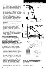
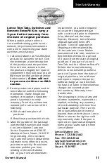
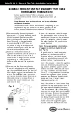
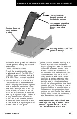
Insert the actuator cable through the
transom. With the actuator loosely
supported, start the provided #14 x
1-1/4" (3.17 cm) stainless steel metal
screws through the upper bracket
and into the transom. MAKInG
SURE TO LEAVE THE SCREWS OnLY
pARTIALLY InSTALLED.
Insert the actuator clevis (mounting
ear) into the top bracket and hold in
the approximate installed location.
pass the actuator cable through
the transom removing slack on the
cable until it is snug. Remove the
actuator from the upper bracket
and finish installing the previously
started #14 x 1-1/4" (3.17 cm)
stainless steel metal screws through
the upper bracket and into the
transom. We recommend using 3M
5200 adhesive caulking to bed the
upper bracket and screws. DO nOT
OVERTIGHTEn.
Attach the actuator to the upper
bracket using the 5/16-18 X 1 3/4"
(4.45 cm) large hex head bolt and
5/16-18 (.79 cm) hex nut provided.
If, however, you are prevented from
drilling a hole through the transom
at the bracket location, using the
3/8" (.95 cm) drill bit, simply drill a
3/8" (.95 cm) hole 4" to 5" (10.16 to
12.7 cm) above the waterline and
insert the cable. Cover the hole and
cable with a clamshell vent sealed
with 3M 5200 for a waterproof and
finished effect.
Assemble actuator connector ends
as instructed in Actuator Deutsch
Connector Instructions insert card
provided.
5. At the helm, determine where the
tactile switch will be installed, locate
the template on page 27 and secure
to helm, cut a circular opening using
a 2" (5.08 cm) hole saw. Before
cutting, make sure the area inside
the helm is clear of wires and other
equipment that could be damaged.
Using the template on page 35, drill
four 3/16" (.48 cm) holes through
the helm.
Secure the switch with the nylon
nuts provided. When mounting the
black control box, keep in mind that
there is a 30" (76.2cm) lead that
attaches to the back of the tactile
switch. Make sure control box is
mounted on a vertical surface with
wires facing down toward the deck.
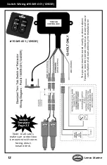
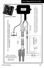
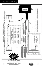
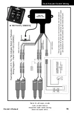
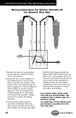
6. Following the trim tab switch wiring
diagram, connect the actuators or
the actuator extension cables to the
switch control box. Be very careful
of sharp edges that may damage
the cable. Remember the left switch
controls the right starboard tab and
the right switch controls the left port
tab.
Please follow the instructions and
drawings carefully.
Call the Lenco Service Department
at 772-288-2662 for technical
assistance.
Trim Tab Installation Instructions
Installation Instructions continued from page 9.
Summary of Contents for 190 InShore 2014 Series
Page 1: ...190IS 190 InShore Series OWNER ASSISTANCE MANUAL Revised 2014...
Page 30: ...28 Appendix 190 IS...
Page 31: ...29 Hydraulic Steering System...
Page 32: ...30...
Page 33: ...31...
Page 34: ...32...
Page 35: ......
Page 36: ......
Page 37: ......
Page 38: ......
Page 39: ......
Page 40: ......
Page 52: ...vi Selection Guide...
Page 58: ...1 6 Selection Guide...
Page 62: ...2 4 Selection Guide...
Page 88: ...4 8 Selection Guide...
Page 138: ...11 2 Selection Guide...


