Mounting the Pump
(Models 401C, 403C, 405C, 401STC,
403STC 405STC)
1. Drill a 1” diameter hole through the transom or hull
bottom. If drilling through the transom, make sure the
hole inside the boat is beneath the waterline outside the
boat when the boat is standing still.
2. Place the pump into the hole with the gasket in place on
the inside of the boat.
3. Tighten the nut on the outside of the hull until you are sure
the gasket ring is tightly sealed. Be careful not to over-
tighten. Make sure outlet is at least parallel with boat
bottom. This helps prevent airlocks.
4. Saw off the excess length of the pickup tube so it is flush
with the outside surface of the nut. In the event you are
using a strainer (Rule Model 73), leave 1/2” beyond the
nut. Make sure the cut is square and the threads de-
burred to allow the debris strainer to fit smoothly.
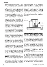
By lifting the locking ring, you can rotate the position of the
discharge nozzle so that the discharge is facing toward the
tank (see diagram below).
(Models 401FC, 403FC 405FC)
Seacock applications
1. Drill a 1” diameter hole through the
transom or hull bottom. If drilling
through the transom, make sure
the hole inside the boat is beneath
the waterline outside the boat
when the boat is standing still.
2. Install a thru-hull pickup tube with a filter grate to prevent
debris from entering the seacock and the pump. Use a
marine sealant on the flat surface of the thruhull where it
will be in contact with the outside surface of the boat and
around the threaded tube on both sides of the hull. Install
the seacock and pump using pipe tape or sealant on all
threaded connections.
3. Screw the pump into the seacock until it is hand tight. Do
not over-tighten.
4. If the pump is mounted horizontally, the output must be
pointed upward to allow air to vent.
KEEP SEACOCK VALVE CLOSED WHEN LIVEWELL IS
NOT IN USE
Electrical
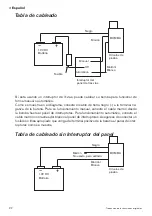
WIRE:
Normal installations require 16 gauge wire.
POLARITY:
Brown pump wire connects to the positive (+)
side of the battery. Black pump wire connects to the negative
(-) side of the battery.
FUSE:
Install proper size fuse & holder in the positive (+)
brown wire between the pump and the battery.
500 GPH pumps (Models 401C, 401STC, 401FC) -
INSTALL A 2.5 AMP FUSE
800 GPH pumps (Models 403C, 403STC, 403FC) -
INSTALL A 5.0 AMP FUSE
1100 GPH pumps (Models 405C, 405STC, 405FC) -
INSTALL A 6.0 AMP FUSE
IMPORTANT - THIS PRODUCT SHOULD BE
INSTALLED WITH THE RECOMMENDED FUSE SIZE
NOTE:
Keep all wire connections and joints above highest
possible water level.
Seal wire connections with a marine sealant to prevent
corrosion.
Hose Connection
Dual Port Option
Each pump is fitted with an additional 1/2” NPT female port
and Hex Plug. This feature allows you to add your washdown
pump without adding another thru-hull fitting.
• Use a marine ribbed hose that will not kink with bends and
is rated for below water line use.
• Hose should run uphill evenly from pump to livewell tank.
You may use a control valve to regulate the flow.
• Use hose clamps when making connections to pump and valve.
Pump Discharge
Can Rotate 360
°
Raise Ring to
Allow Pump
to Rotate
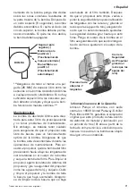
THE PUMP IS BELOW
THE
WATERLINE.
WATER CAN COME
INTO THE BOAT THROUGH THE PUMP IF THE
HOSE IS NOT CONNECTED TIGHTLY TO THE PUMP.
CAUTION
© Copyright 2006, ITT Industries
All Rights Reserved
Form: 950-0213
Rev. A 06/2006
Rule
1 Kondelin Road
Gloucester, MA 01930
Tel: 978-281-0573
Fax: 978-283-2619
Made in China
www.rule-industries.com
Summary of Contents for 190 InShore 2014 Series
Page 1: ...190IS 190 InShore Series OWNER ASSISTANCE MANUAL Revised 2014...
Page 30: ...28 Appendix 190 IS...
Page 31: ...29 Hydraulic Steering System...
Page 32: ...30...
Page 33: ...31...
Page 34: ...32...
Page 35: ......
Page 36: ......
Page 37: ......
Page 38: ......
Page 39: ......
Page 40: ......
Page 52: ...vi Selection Guide...
Page 58: ...1 6 Selection Guide...
Page 62: ...2 4 Selection Guide...
Page 88: ...4 8 Selection Guide...
Page 138: ...11 2 Selection Guide...

