


14
5
단계
.
케이블
및
전원
커넥터
연결하기
:
c. 4
핀
전원
케이블을
연결합니다
ATX_12V 4
핀
전원
커넥터는
전원을
CPU
에
공급하기
위해
사용됩니다
. 4
핀
전원
케이블
설치시에는
,
전원
케이블의
걸쇠가
ATX_12V
커넥터와
완벽하게
맞아야
합니다
.
b. SATA
전원
커넥터를
SATA
장치에
연결합
니다
a. SATA
하드
드라이브를
SATA
케이블에
연결합니다
d. 4
핀
전원
케이블을
연결합니다
24
핀
전원
케이블
연결시
전원
케이블과
ATX
커넥터의
걸쇠가
완벽하게
맞아야
합니다
.
한국어
일단
위의
단계들이
완료되면
,
키보드
,
마우스
,
모니터
등과
같은
주변기기들을
연결
합니다
.
그런
후에
,
전원을 연결하고
시스템을
켭니다
.
모든
필수
소프트웨어를
설치
합니다
.
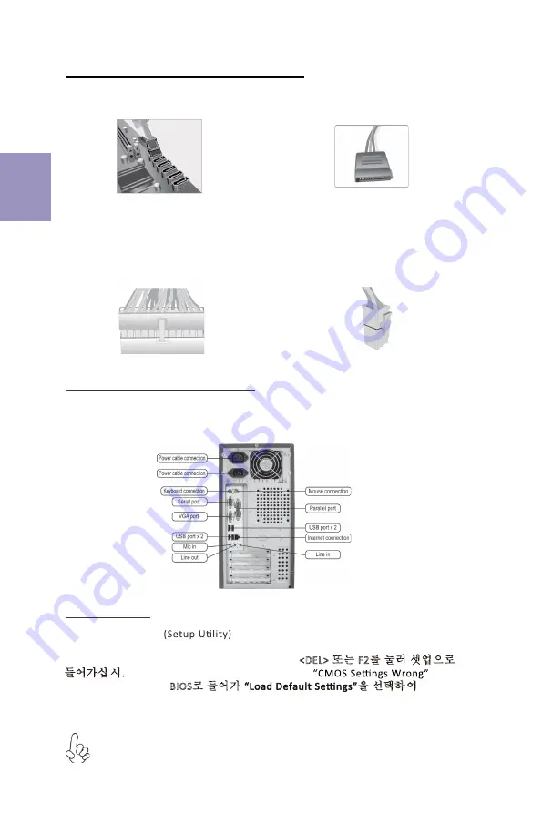
6
단계
.
케이스의
포트
연결하기
:
BIOS
사용하기
BIOS
셋업
유틸리티
는
시스템의
환경설정
상태를
표시하며
시스템
매개변수를
설정하기
위한
옵션을
제공합니다
.
시스템의
전원을
켜면
, BIOS
는
Power-On Self Test (POST)
루틴을 실행합니다
,
<DEL>
또는
F2
를
눌러
셋업으로
들어가십 시.
오
처음으로 전원을 켜면 POST 화면에
메시지가
나타날 수 있습니다
.
BIOS
로
들어가
을
선택하 여
기본
CMOS
설정값을
재설정합니다
. (CPU,
메모리
등과
같은
시스템
변경할 때에도
본 메뉴가
나타날
수
있습니다
.)
설치절차는
사용된
케이스
및
장치의
유형에
따라
다를
수
있습니다
.
Summary of Contents for B450AM4-M
Page 2: ...ii B450AM4 M USER MANUAL Memo...
Page 5: ...B450AM4 M USER MANUAL 3 Motherboard Components...
Page 13: ...11 1 CPU CPU 2 2 1 3 3 1 I O I O 2 2 3 2 I O I O 4 1 1 C P U C P U C P U C P U 1 2 CPU CPU...
Page 15: ...13 1 CPU CPU 2 2 1 DIMM 3 3 1 I O I O 2 2 DIMM DIMM 3 2 I O 4 1 1 90 CPU CPU 1 2 CPU CPU...
Page 19: ...17 1 2 CPU CPU CPU 2 2 3 2 2 1 3 1 1 1 CPU 90 CPU 90...
Page 20: ...18 b c d a...
Page 21: ...19 DIMM 8 9 J Q X Z b X j z 9 X 8...
Page 22: ...20...