ECS B450AM4-M User Manual Download Page 11

9

English

Hardware Installation Guide

Installation Steps

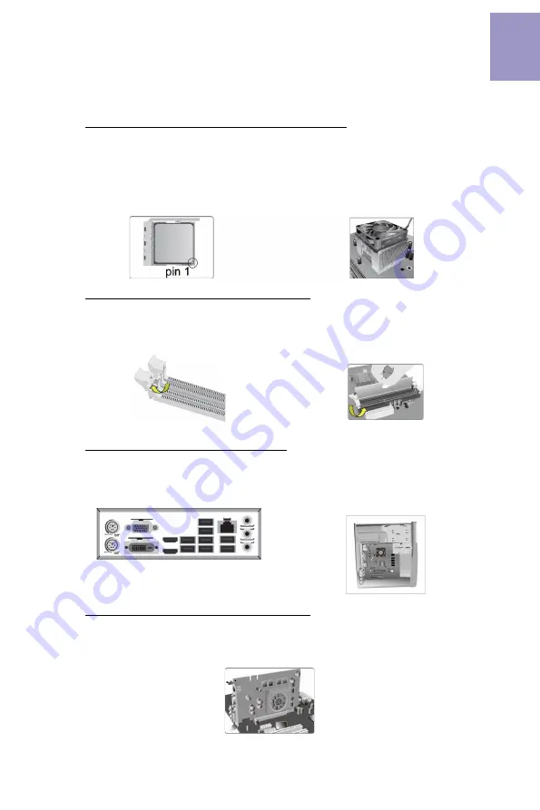
Step 2. Installation of Memory Modules:

2-1. Unfasten the latches on each side
of the DIMM slots.

Step 3. Installation of Motherboard:

3-1. Replace the back I/O plate of the
case with the I/O shield provided in
motherboard’s package.

2-2. Firmly press the DIMM down until it
seats correctly.  Make sure the slot
latches are levered upwards and latch
on the edge of the DIMM.

3-2. Place the motherboard within the
case by positioning it into the I/O plate.
Secure the motherboard to the case
with screws.


Step 4. Installation of an Expansion card:

Remove the metal located on the slot and then insert the expansion card into the
slot. Press the card firmly to make sure it is fully inserted into its slot. And then
return the screw back to its position.

Step 1. Installation of the CPU and CPU Cooler:

1-1. Position lever at a 90 degree angle.
Locate the CPU cut edge (the comer
with the pin hold noticeably missing).
Align and insert the CPU correctly, then
press the metal lever back into its
original position.

1-2. 

Apply thermal grease on top of the

CPU. Put the CPU Fan down on the
retention module and flip the levers
over the heat sink in place.

Summary of Contents for B450AM4-M

Page 1: ...reface i Brief Introduction 1 Specifications 1 MotherboardComponents 3 HeaderPinDefinitionandJumperSettings 5 I OPorts 8 Multi language Quick Installation Guide 9 English 9 SimplifiedChinese 11 Korean...

Page 2: ...ii B450AM4 M USER MANUAL Memo...

Page 3: ...2 0 ports 4 x USB 3 0 ports 1 x RJ45 LAN connector 1 x Audio port 1x Line in 1x Line out 1x Mic_in Rear Rear Panel I O Realtek RTL8111GN 10 100 1000 Fast Ethernet Controller Wake on LAN and remote wa...

Page 4: ...BIOS parameters copied to the flash disk Supports Pgup clear CMOS Hotkey Has PS2 KB Model only System BIOS Form Factor Micro ATX Size 244mm x 244mm 1 x USB 3 1 Gen1 header supports additional two USB...

Page 5: ...B450AM4 M USER MANUAL 3 Motherboard Components...

Page 6: ...SB3F Front Panel USB 3 1 Gen1 header 11 F_USB2 Front Panel USB 2 0 header 12 F_USB1 Front Panel USB 2 0 header 13 SYS_FAN1 4 pin System cooling fan connector 14 BZ Buzzer 15 F_PANEL Front panel switch...

Page 7: ...PANEL Hard disk LED Hard disk LED Reset Switch Reset Switch Reserved Power Switch Power Switch MSG LED MSG LED Ground Ground Power 5V Power 5V Ground NC USB Port B USB Port A USB Port A USB Port B USB...

Page 8: ...ower 12V SYS_FAN1 2 1 Sensor PWM System Ground Power 12V 1 LPT 1 INIT Ground SLCT Ground Key Ground Ground AFD ERROR Ground Ground Ground Ground PD1 PD5 PD2 PD6 SLCT PD4 PD3 STROBE PD0 PD7 ACK BUSK PE...

Page 9: ...ort1 D USB3 ICC Port2 D USB3 ICC Port2 D USB3 ICC Port1 SuperSpeed Rx USB3 ICC Port2 SuperSpeed Rx USB3 ICC Port1 SuperSpeed Rx USB3 ICC Port2 SuperSpeed Rx USB3 ICC Port1 SuperSpeed Tx USB3 ICC Port2...

Page 10: ...e USB 3 1 ports to connect USB 3 1 devices 8 USB 3 0 Ports Use the USB 3 0 ports to connect USB 3 0 devices 9 LAN Port Connect an RJ 45 jack to the LAN port to connect your computer to the Network 10...

Page 11: ...I O plate Secure the motherboard to the case with screws Step 4 Installation of an Expansion card Remove the metal located on the slot and then insert the expansion card into the slot Press the card...

Page 12: ...A cable d Connect 4 pin power cable Please note that when installing 24 pin power cable the latches of power cable and the ATX connector match perfectly The sequence of installation may differ dependi...

Page 13: ...11 1 CPU CPU 2 2 1 3 3 1 I O I O 2 2 3 2 I O I O 4 1 1 C P U C P U C P U C P U 1 2 CPU CPU...

Page 14: ...12 5 c 24 4 CPU b SATA SATA a SATA SATA d 4 6 BIOS BIOS BIOS POST DEL F2 BIOS POST BIOS BIOS CPU...

Page 15: ...13 1 CPU CPU 2 2 1 DIMM 3 3 1 I O I O 2 2 DIMM DIMM 3 2 I O 4 1 1 90 CPU CPU 1 2 CPU CPU...

Page 16: ...14 5 c 4 ATX_12V 4 CPU 4 ATX_12V b SATA SATA a SATA SATA d 4 24 ATX 6 BIOS BIOS BIOS Power On Self Test POST DEL F2 POST BIOS CMOS CPU...

Page 17: ...pelat I O Kencangkan motherboard pada casing dengan sekrup Bahasa Indonesia Langkah 4 Pemasangan kartu Ekspansi Lepaskan logam yang terletak pada slot lalu masukkan kartu dengan kencang untuk ahwa ka...

Page 18: ...ia Setelah langkah langkah di atas selesai harap monitor dll Lalu sambungkan daya dan nyalakan sistem Harap pasang semua perangkat lunak yang dibutuhkan Langkah 6 Menyambungkan port pada casing Menggu...

Page 19: ...17 1 2 CPU CPU CPU 2 2 3 2 2 1 3 1 1 1 CPU 90 CPU 90...

Page 20: ...18 b c d a...

Page 21: ...19 DIMM 8 9 J Q X Z b X j z 9 X 8...

Page 22: ...20...

Reviews: