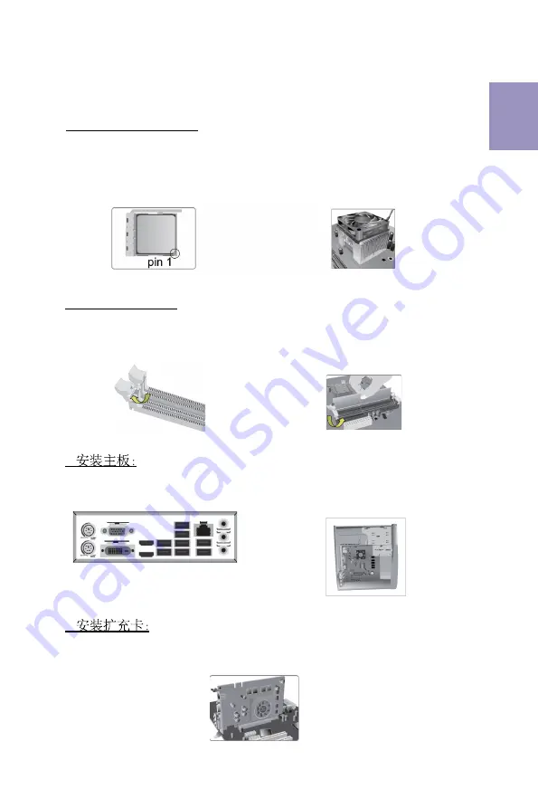
ECS B450AM4-M User Manual Download Page 13

11

1.

安装

CPU

CPU

风扇:

硬件安装指南

安装步骤

2.

安装记忆体模组:

2-1. 

向外扳开内存插槽两端的卡扣。

3.

3-1. 

取下机箱后面的

I/O

挡板,换上主

板附带的

I/O

弹片。

2-2. 

对准内存插槽,将内存条往下按直至完

全插入。正确安装后插槽两端的卡扣会自动
锁住内存条边 缘。

3-2. 

将主板的后

I/O

对准机箱上的

I/O

挡板孔

位,放入机箱并以螺丝固定。


4.

移除机箱后面的扩充金属挡板,确认扩充卡完全插入扩展 槽后,重新拧上螺丝。

简体中文

1-1. 

C P U

插槽旁的固定推杆拉到垂直

状态。


C P U

上金色的三角形标示对准

C P U

插槽上三角形标示,小心地将

C P U

正确置入插槽,然后把固定推杆放下到
锁定位置。

1-2. 

CPU

上涂好一层平滑的散热膏将

CPU

风扇固定在散热片上方。


Summary of Contents for B450AM4-M

Page 1: ...reface i Brief Introduction 1 Specifications 1 MotherboardComponents 3 HeaderPinDefinitionandJumperSettings 5 I OPorts 8 Multi language Quick Installation Guide 9 English 9 SimplifiedChinese 11 Korean...

Page 2: ...ii B450AM4 M USER MANUAL Memo...

Page 3: ...2 0 ports 4 x USB 3 0 ports 1 x RJ45 LAN connector 1 x Audio port 1x Line in 1x Line out 1x Mic_in Rear Rear Panel I O Realtek RTL8111GN 10 100 1000 Fast Ethernet Controller Wake on LAN and remote wa...

Page 4: ...BIOS parameters copied to the flash disk Supports Pgup clear CMOS Hotkey Has PS2 KB Model only System BIOS Form Factor Micro ATX Size 244mm x 244mm 1 x USB 3 1 Gen1 header supports additional two USB...

Page 5: ...B450AM4 M USER MANUAL 3 Motherboard Components...

Page 6: ...SB3F Front Panel USB 3 1 Gen1 header 11 F_USB2 Front Panel USB 2 0 header 12 F_USB1 Front Panel USB 2 0 header 13 SYS_FAN1 4 pin System cooling fan connector 14 BZ Buzzer 15 F_PANEL Front panel switch...

Page 7: ...PANEL Hard disk LED Hard disk LED Reset Switch Reset Switch Reserved Power Switch Power Switch MSG LED MSG LED Ground Ground Power 5V Power 5V Ground NC USB Port B USB Port A USB Port A USB Port B USB...

Page 8: ...ower 12V SYS_FAN1 2 1 Sensor PWM System Ground Power 12V 1 LPT 1 INIT Ground SLCT Ground Key Ground Ground AFD ERROR Ground Ground Ground Ground PD1 PD5 PD2 PD6 SLCT PD4 PD3 STROBE PD0 PD7 ACK BUSK PE...

Page 9: ...ort1 D USB3 ICC Port2 D USB3 ICC Port2 D USB3 ICC Port1 SuperSpeed Rx USB3 ICC Port2 SuperSpeed Rx USB3 ICC Port1 SuperSpeed Rx USB3 ICC Port2 SuperSpeed Rx USB3 ICC Port1 SuperSpeed Tx USB3 ICC Port2...

Page 10: ...e USB 3 1 ports to connect USB 3 1 devices 8 USB 3 0 Ports Use the USB 3 0 ports to connect USB 3 0 devices 9 LAN Port Connect an RJ 45 jack to the LAN port to connect your computer to the Network 10...

Page 11: ...I O plate Secure the motherboard to the case with screws Step 4 Installation of an Expansion card Remove the metal located on the slot and then insert the expansion card into the slot Press the card...

Page 12: ...A cable d Connect 4 pin power cable Please note that when installing 24 pin power cable the latches of power cable and the ATX connector match perfectly The sequence of installation may differ dependi...

Page 13: ...11 1 CPU CPU 2 2 1 3 3 1 I O I O 2 2 3 2 I O I O 4 1 1 C P U C P U C P U C P U 1 2 CPU CPU...

Page 14: ...12 5 c 24 4 CPU b SATA SATA a SATA SATA d 4 6 BIOS BIOS BIOS POST DEL F2 BIOS POST BIOS BIOS CPU...

Page 15: ...13 1 CPU CPU 2 2 1 DIMM 3 3 1 I O I O 2 2 DIMM DIMM 3 2 I O 4 1 1 90 CPU CPU 1 2 CPU CPU...

Page 16: ...14 5 c 4 ATX_12V 4 CPU 4 ATX_12V b SATA SATA a SATA SATA d 4 24 ATX 6 BIOS BIOS BIOS Power On Self Test POST DEL F2 POST BIOS CMOS CPU...

Page 17: ...pelat I O Kencangkan motherboard pada casing dengan sekrup Bahasa Indonesia Langkah 4 Pemasangan kartu Ekspansi Lepaskan logam yang terletak pada slot lalu masukkan kartu dengan kencang untuk ahwa ka...

Page 18: ...ia Setelah langkah langkah di atas selesai harap monitor dll Lalu sambungkan daya dan nyalakan sistem Harap pasang semua perangkat lunak yang dibutuhkan Langkah 6 Menyambungkan port pada casing Menggu...

Page 19: ...17 1 2 CPU CPU CPU 2 2 3 2 2 1 3 1 1 1 CPU 90 CPU 90...

Page 20: ...18 b c d a...

Page 21: ...19 DIMM 8 9 J Q X Z b X j z 9 X 8...

Page 22: ...20...

Reviews: