


13
모듈 설치하기:
1
단계
. CPU
와
CPU
하드웨어
설치
가이드
단계별
설치
방법
2
단계
.
메모리
2-1. D I M M
슬 롯 의
각
측 면 에
있 는
걸 쇠 를
풉 니 다
.
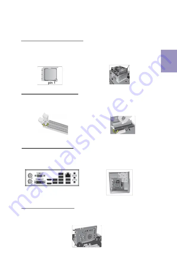
3
단계
.
마더보드
설치하기:
3-1.
케 이 스 의
후 면
I / O
플 레 이 트 를
마 더 보 드 의
패 키 지 에
제 공 된
I / O
실 드 로
교 체 합 니 다
.
2-2. DIMM
이
정확하게
설치될
때까지
단
단히
누릅니다
.
슬롯
걸쇠를
위로
DIMM의 가장자리를 잠급니다.
.
3-2.
마 더 보 드 를
I / O
플 레 이 트 에
위 치 시
켜
케 이 스
내 에.
스 크 류 로
마 더 보 드 를
케 이 스 에
고 정 시 킵 니 다
.
쿨러
설치하기:
한국어
올려
4
단계
.
확장
카드 설치하기:
슬롯에
설치되어 있는
금속을
제거하고
확장
카드를
해당
슬롯에
삽입합니다
.
슬롯에
완전히
삽입될
수
있도록
카드를
단단히
누릅니다
.
스크류를
다시
제
자리에
체결합니다
.
1-1.
레버가
90
도
각이
되게
합니다.
CPU
절단
모서리
(
눈에
띄게
핀
고정
장치가
누락되어
있는
모서리
)
의
위치를확인합
니다
. CPU
를
정확히
삽입한
후
금속 레버
를
눌러
원위치가
되게
합니다.
1-2.
써멀
그리스를
CPU
상단에
도포합니다
CPU
팬을
고정용
모듈에
체결한
후
레버를
채워
히트싱크를
제
위치에
고정시킵니다.
.
Summary of Contents for B450AM4-M
Page 2: ...ii B450AM4 M USER MANUAL Memo...
Page 5: ...B450AM4 M USER MANUAL 3 Motherboard Components...
Page 13: ...11 1 CPU CPU 2 2 1 3 3 1 I O I O 2 2 3 2 I O I O 4 1 1 C P U C P U C P U C P U 1 2 CPU CPU...
Page 15: ...13 1 CPU CPU 2 2 1 DIMM 3 3 1 I O I O 2 2 DIMM DIMM 3 2 I O 4 1 1 90 CPU CPU 1 2 CPU CPU...
Page 19: ...17 1 2 CPU CPU CPU 2 2 3 2 2 1 3 1 1 1 CPU 90 CPU 90...
Page 20: ...18 b c d a...
Page 21: ...19 DIMM 8 9 J Q X Z b X j z 9 X 8...
Page 22: ...20...