background image

13

RefRIgeRANT PROCeSSINg

Refrigerant Processing

1. 

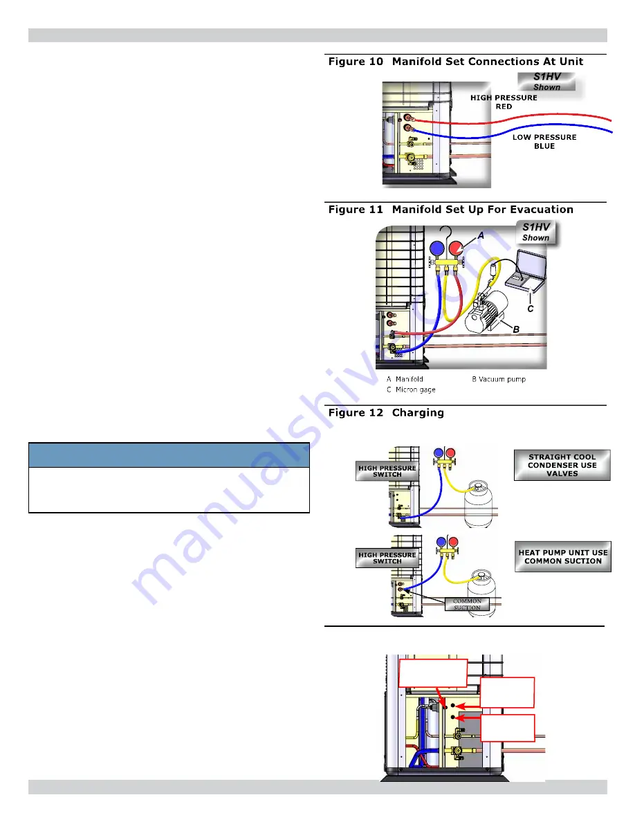
Attach manifold set, vacuum pump, & Micron Gauge. 

See Figure 10.

2. 

Evacuate line to 500 microns or less to insure all 

moisture has been removed and there are no leaks. 

See Figure 11.

A. 

 Evacuate

B. 

Pressurize with 100psi N2 or Nitrogen 

C. 

Evacuate again

D. 

Charge with R410A

3. 

verify evacuation and leak free joints. Back-seat valves 

(counter-clockwise) to open and allow factory charge to 

fill lines and indoor unit. See  Figure 13.

Refer to refrigerant charge table for specified charge.

4. 

Charge to proper weight. Charge based on feet of 

interconnect.

  Only add/remove R410A in liquid 

form

. See 

Table 5, Page 14

.


5. 

Install all panels removed to this point. Panels are re

-

quired for proper air flow.

All systems require field charge adjustments. Refer to 

“Refrigerant Charge Tables” for proper weight charge 

and Operation Charts for proper system pressures and 

temperatures at different outdoor conditions. Sub-cool 

should be used for final system charge.

Charge with dial-a-charge or weighed in with scale.

NOTICe

It is illegal to discharge refrigerant into the 

atmosphere. Use proper reclaiming methods & 

equipment when installing or servicing this unit.

Units are delivered pre-charged with refrigerant for 

condenser coil and air handler. Charging of field installed 

piping is required. Refer to refrigerant charge table for 

proper amount to be added for applications interconnect 

piping. Unit service valves are solid brass, for sweat 

connections.

• Measure all heat pump saturated suction pressures at 

Common Suction Port

 not vapor service valve.  

• Common Suction Port

 includes pressure drop and 

temperature increase through reversing valve resulting 

in more accurate and complete system charge. 

• Port may also be used to charge system in heating 

mode when both sides of line set are at high system 

pressures or to determine saturated evaporator 

pressure while in heating mode.

figure 13  Common Suction, Common 

Discharge, & High pressure Switch

COMMON 

DISCHARge 

PORT

HIgH PReSSURe 

SWITCH

COMMON 

SUCTION 

PORT

Summary of Contents for UNHV09

Page 1: ...l Capacities UNHV09 UNHV12 UNHV18 UNHV24 UNHV30 UNHV36 Units 9 000 12 000 18 000 24 000 29 800 33 400 Btuh COOL 2 6 3 5 5 3 7 0 8 8 9 8 kW 8 800 10 000 18 000 21 000 26 000 26 400 Btuh HEAT 2 5 2 6 5 0 5 6 7 6 7 7 kW Installation Operation and Maintenance Manual ECR International Inc 2201 Dwyer Avenue Utica NY 13501 web site www ecrinternational com ...

Page 2: ...eld Controller Operation 29 Wired Wall Control Operation 33 Controller Features 34 Controller Fault Conditions 35 Maintenance 36 Troubleshooting 37 Frequently Asked Questions 39 Specifications And Dimensions 40 Unhv System Options 41 Test Unit Performance Data Sheet 42 Table of Contents Information and specifications outlined in this manual in effect at the time of printing of this manual Manufact...

Page 3: ...l to verify unit has been installed correctly Run unit for one complete cycle to verify proper function To obtain technical service or warranty assistance during or after installation contact your local representative Visit our web site www enviromaster com for local representative listing For further assistance call 1 800 325 5479 When calling for assistance please have following information read...

Page 4: ...y grounded electrical supply Do not fail to properly ground this unit Check the rating plate on the unit before installation to verify voltage shown is same as electric supply to the unit Rating plate is located on top panel only Tampering voids all warranties DANGER Indicates a hazardous situation which if not avoided WILL result in death or serious injury WARNING Indicates a hazardous situation ...

Page 5: ... drainage and or power 8 Opening x bottom right front corner of cabinet for condensate drain tube routing when unit is ceiling mounted 9 Refrigeration and condensate draining connections are located in this area 10 Electrical connections are located in this area 11 Location of item 7 above 12 1 x 3 knockout each side panel for refrigeration tubing condensate drainage and or power 13 1 x 3 knockout...

Page 6: ...umidity Anti Short Cycle Compressor Protection Minimum ON time for heating and cooling eliminates room temperature droop and system short cycling Freeze Protection Prevents air handlers freeze up Test operation Allows testing after installation Runs at rate condition speeds for set ups and charging Non volatile back up memory maintains control settings for indefinite period during power outage Whe...

Page 7: ...ooth surface such as wallboard or similar material Mounting to masonry block wall provide smooth barrier between unit and masonry block surface to absorb potential vibration and prevent formation of condensation on the wall Unit can be suspended from ceiling using threaded rods Installation Considerations Determine best location for mounting unit for room air circulation Locate outdoor and indoor ...

Page 8: ...placed PVC pipe 3 or 4 I D may be used as pipe chase ceiling Mounted Wall Mounted 5 Determine appropriate hole size Cut through wall or ceiling 6 Remove return air grille by removing screws on front of grille Lift grille off See Figure 3 7 Remove rest of painted cabinet See Figure 3 A Completely remove center screws B Loosen do not remove four remaining screws 5 16 slotted hex so there is approxim...

Page 9: ...ult in death or serious injury Ceiling Mounting Threaded rods may be inserted through mounting holes to suspend unit from ceiling supports Verify unit is mounted to support its weight See Figure 4 Wall Mounting Secure unit to wall with wood screws or anchors for masonry using mounting holes located in back panel of unit See Figure 5 Figure 4 Ceiling Mounting threaded rod Figure 5 Wall Mounting mou...

Page 10: ...1 5mm per 10 1m There must not be any uphill gradients C When multiple units are connected to common condensate drain insure drain is large enough to handle volume of condensate from all units Recommend having air vent in condensate hose to prevent air locks D If using accessory condensate pump follow pump manufacturer instructions Use condensate hose tie downs in ceiling mount applications Conden...

Page 11: ...rough wall openings Insulate both lines Isolate tubing from transmitting vibration to building or unit and avoid contact with sharp edges Wrap refrigeration valves with wet rag heat sink to protect valves while brazing See Figure 9 Page 12 DO NOT use suction line size larger than condenser service valve connection This can harm compressor Install reducer when used only at air handler connection Mo...

Page 12: ...ng with a wet rag heat sink before brazing See Figure 9 3 Use a shield to protect the paint as shown in Figure 9 The shield can be made from scrap metal 4 Braze tubing into fittings Pressure test all field installed piping with nitrogen Using suitable vacuum pump evacuate tubing and indoor unit to 500 microns or less with service valves remaining front seated closed Figure 8 Clean ends of tubing F...

Page 13: ...rent outdoor conditions Sub cool should be used for final system charge Charge with dial a charge or weighed in with scale NOTICE It is illegal to discharge refrigerant into the atmosphere Use proper reclaiming methods equipment when installing or servicing this unit Units are delivered pre charged with refrigerant for condenser coil and air handler Charging of field installed piping is required R...

Page 14: ...Per Foot Factory Charge S1CV9000 CAHV09 25 oz ft 23 g m 39 5oz 1120g S1CV2000 CAHV12 25 oz ft 23 g m 39 5oz 1120g S1CV8000 CAHV18 64 oz ft 59 g m 54 0oz 1531g S1CV4000 CAHV24 64 oz ft 59 g m 54 0oz 1531g S1CV3000 CAHV30 64 oz ft 59 g m 90 0oz 2551g S1CV6000 CAHV36 64 oz ft 59 g m 90 0oz 2551g S1HV9000 CAHV09 25 oz ft 23 g m 39 5oz 1120g S1HV2000 CAHV12 25 oz ft 23 g m 39 5oz 1120g S1HV8000 CAHV18 ...

Page 15: ...er wire for ampacity rating 2 Each unit must have separate branch circuit protected by time delay fuse or breaker Refer to unit rating plate for proper wire and breaker or time delay fuse size 3 Inspect existing wiring for any defects such as cut or frayed wires Replace if any such wiring if found 4 See Figure 14 for electrical panel location Units rated 208 230V primary side of transformer is fac...

Page 16: ...ation in control box Terminate ALL unused wires with wire nut or crimp connector Low Voltage Electrical Wiring All low voltage interconnect wiring must be at least 18 AWG 24V control transformer is located in air handler Provides low voltage control power to both air handler and condenser Low voltage connections Figure 15 Remove Control Box Cover Screws To Access High Voltage Wiring Compartment Re...

Page 17: ...mp systems utilize six 6 low voltage interconnecting wires between indoor and outdoor units Each wire COM1 COM2 SC 24 VDC RV and RV should connect to same named terminal indoor and outdoor See Figure 19 RV signal is alternating current as long as both indoor RV connections are connected to outdoor RV connections system will function correctly The other four 4 wires are polarized and must be connec...

Page 18: ...al 15 foot cable may be daisy chained total of 2 cables or 30 feet of interconnect cable Do not splice cables together on site Hand held remote is required to enter Test Mode Wired wall control has limited capabilities for technician testing Heat Pump Applications Heat pump operation requires connection of 2 RV termi nals between outdoor unit to indoor unit See Figure 22 Page 19 Reversing valve is...

Page 19: ...19 Electrical Wiring Figure 21 Wired Wall Controller Configuration Cooling Only Figure 22 Wired Wall Controller Configuration Heat Pump ...

Page 20: ...abinet cannot slide replace screws after cabinet is in position 2 Loosely tighten upper screws 3 Loosely tighten 2 lower cabinet screws 4 Insert and tighten center screws 5 Tighten all six screws to secure cabinet See Figure 24 1 Replace grille 2 Verify filter is in place on back of grille Figure 23 Replace Tighten Top Bottom And Center Cabinet Screws Loosen top screws Remove center screws Loosen ...

Page 21: ...inuously adjusts refrigerant flow to maintain 15ºF 8 3ºC superheat at compressor Expanded refrigerant froth travels through small diameter tube of line set to air handler where heat is transferred into refrigerant Once refrigerant evaporates super heated vapor returns to condenser via large diameter tube Refrigerant expansion occurs in outdoor unit both tubes in line set require insulation As temp...

Page 22: ... coil defrost are in place whenever compressor runs in Heating Mode Condenser mounted Electronic Expansion Valve EXV continuously adjusts refrigerant flow to maintain 15ºF 8 3ºC superheat at compressor Refrigerant vapor travels through large diameter tube of line set to air handler where heat is transferred into air Once refrigerant is condensed sub cooled liquid returns to condenser via small dia...

Page 23: ...trol Unit Operation is dependent on room temperature It may be necessary to warm room before testing unit s cooling abilities Before Starting The Unit Become familiar with outdoor unit s start up instructions for specific requirements and procedures 1 Remove any tools or other obstructions 2 Verify filter is in place 3 Verify unit is level and plumb 4 Separate any refrigerant lines that contact ea...

Page 24: ...le between manual operation and Pre programmed 7 day run mode Configuration Set Time or Program ming mode press to enter the next selection Press to toggle Timer mode on off While in Heating or Cooling mode press for 5 seconds to enter test mode Intended for service only Holds the unit at a fixed speed While in Heating or Cooling press for 5s enters Turbo mode for 30m MODE PROG With unit in OFF mo...

Page 25: ...ss to decrease the setting LEFT ARROW Press for the previous item selection RIGHT ARROW Press for the next item selection FAN Press to toggle between fan modes High Med Low or Auto PROGRAM Normal operation Press to toggle between manual operation and Pre programmed 7 day run mode Configuration Set Time or Programming mode TIMER Press to toggle Timer mode on off TURBO While in Heating or Cooling pr...

Page 26: ...8 to record settings Day of week Mon Tue Wed Thu Fri Sat Sun The louver is closed when the fan is off Period of day Morning Day Evening Night The periods provide four time settings to initiate a change in cooling heating setpoints They allow adjustments for setback such as night setback daytime setback and occupied settings for residential applications Set the hour minute for each time as well as ...

Page 27: ...ith room temperature at or above 71 F heating is on with room temperature at or below 65 F Check filter time 05 F Lt 2 5 7 10 12 250 hours 500 hours 750 hours 1000 hours 1250 hours 10 Set this time for automatic notice of time to change the filter At the end of the time period the control will display a FILTER CHECK warning This warning will also appear if four evaporator freeze ups should occur i...

Page 28: ... Temp Time Temp Time Temp Time Temp Monday Tuesday Wednes day Thursday Friday Saturday Sunday To copy the settings from any day to the entire week 1 Select the day to be copied 2 Simultaneously press the Fan and Prog buttons for three sec onds Setting the Controller Table 8 Programming Schedule When Using 7 Day Programming ...

Page 29: ...s hibernate mode and display goes dark if there is no activity on remote for ten minutes Pressing any button awakens remote while in hibernate mode Remote returns to mode it was in prior to entering hibernate mode Power Pressing POWER button momentarily switches unit either on or off 1 OFF mode LCD displays time of day and day of week 2 ON mode LCD displays room temperature mode of operation Cooli...

Page 30: ...ut Electric Heat Heat Pump Unit Outdoors EMI heat pumps are intended to operate with indoor air handler with optional electric heat If indoor air handler without electric heat is matched with heat pump condenser system will deliver cold air during defrost Heat pump operation without electric heat control must first be configured properly See Heat Source ON Table 7 pg 27 Heat Pump OFF Table 7 page ...

Page 31: ...es to boost room temperature back up to setpoint temperature If room temperature rises above setpoint temperature by 2 degrees heating stops and cooling continues to bring room temperature back down to setpoint temperature Hand Held Controller Operation Fan operates continuously at low speed while in Dry mode In order to prevent short cycling there is 2 minute minimum on time for both cooling and ...

Page 32: ...ry or Fan modes 3 Pressing PROGRAM button momentarily enters or exits Pre Programmed Run mode 4 The word PROGRAM appears in LCD display 5 The setpoint changes to programmed setting at se lected time To use Pre Programmed Run mode enter program settings through 7 Day Programming mode 1 Select mode of operation Cooling Heating Auto and press PROGRAM button to enter Pre Program Run mode 2 As time pas...

Page 33: ...ration with electric heat control must be configured properly Wired Wall Control Heat source ON See Table 7 Page 27 Wired Wall Controller controls call for electric heat opera tion On or Off After connecting controller to unit place system switch in Heat mode Adjust set point temperature above room temperature Electric heat energizes with indoor fan motor Heating continues so long as set point rem...

Page 34: ...eat pump mode Minimum Run Time Minimum on time prevents compressor or heat source from cycling off prematurely Minimum ON time for both compressor and electric heat is 2 minutes Drain Pan Sensor Drain pan sensors monitor condensate level in each of unit s drain pans Should water in either pan reach criti cal level monitor automatically signals main control unit Microprocessor switches off condensi...

Page 35: ...flow On 10 Condenser coil temperature too high or low Check system air flow and sensor On 11 Suction temperature too high or low Check system air flow and module On 12 Outdoors ambient temperature too high or low Check outdoor ambient temperature sensor On 13 Discharge temperature fault too high or low Failure for sensor or circuit detection On 15 Communication failure indoor or outdoor Check wire...

Page 36: ...lter dry before replacing 3 Replace filters clips and front grille before operating unit WARNING DO NOT operate unit without filter and front grille in place 4 Vacuum dust from return air grille and coil surface when cleaning filter See Figure 30 5 Wipe chassis with damp cloth when needed See Figure 31 Maintenance WARNING Electrical shock hazard Before removing access panels verify all power is di...

Page 37: ...by a qualified service agency Annual system check is recommended Low Voltage Controls Cooling Only Units Cooling only units utilize 4 low volt interconnecting wires between indoor unit and outdoor Air handlers with unit mounted controls require contacts wired to same name indoors and outdoors COM1 COM2 SC and 24DC COM1 and COM2 carry serial digital communications between indoor and outdoor units T...

Page 38: ... volt control power to both indoor air handler and outdoor condenser between SC and 24VDC terminals This is DC voltage use proper scale on the meter Cooling EMI heat pump systems utilize Reversing Valve energized in Cooling mode and de energized in Heating mode When 24 Volts ac exists between RV and RV either indoors or outdoors system is in cooling mode As long as system is in Cooling mode 24 Vol...

Page 39: ...protection to prevent freeze up from occurring If freeze up does occur check the following Check freeze sensor is located in lowest part of coil Generally this is where freeze up begins Check freeze sensor is inserted fully and snug in coil fin If not another location may need to be selected Take care not to insert sensor directly into coil tube insert sensor between two tubes Check indoor air fil...

Page 40: ...NHV18 UNHV24 26 660 11 279 51 1308 116 53 UNHV30 UNHV36 27 699 12 314 62 1575 153 69 Model High speed CFM l s Medium speed CFM l s Low speed CFM l s Coil FPM m s Throw feet m Observed sound values dBA UNHV 09 12 425 200 400 188 375 175 Dry 900 4 6 15 4 6 51 UNHV 18 24 700 350 625 300 550 250 Dry 1 225 6 2 24 7 3 56 UNHV 30 36 1000 470 900 425 825 400 Dry 1 250 6 4 27 8 2 50 MODEL VOLTS HZ PH FAN R...

Page 41: ...Table 15 Heat Pump System With Universal Units Condenser Wall Units Cooling Btuh Heating Btuh SEER HSPF SHR EER COP Ref S1HV9000 UNHV09 9 000 8 800 16 7 8 2 0 75 13 5 3 2 R410A S1HV2000 UNHV12 12 000 10 000 17 0 8 5 0 66 12 0 3 0 R410A S1HV8000 UNHV18 18 000 18 000 17 0 9 5 0 73 13 0 3 5 R410A S1HV4000 UNHV24 24 000 21 000 17 0 9 5 0 67 11 0 3 2 R410A S1HV3000 UNHV30 29 800 26 000 14 5 7 7 0 71 10...

Page 42: ... Air handlers Entering Air DB Air handlers Entering Air WB Air handlers Leaving Air DB Air handlers Leaving Air WB Outdoor Section Entering Air Leaving Air Temperature Split Operating Pressures Compressor Suction PSIG Compressor Discharge PSIG Power Input Compressor Volts Compressor Amps OD Fan Motor Volts OD Fan Motor Amps ID Fan Motor Volts ID Fan Motor Amps Total Volts Total Amps Temperatures D...

Page 43: ...43 NOTES ...

Page 44: ...Phone 1 800 228 9364 Fax 1 800 232 9364 2201 Dwyer Avenue Utica NY 13501 ...

Reviews: