ECR International Olsen OSVB II Series Installation, Operation & Maintenance Manual Download Page 18

18

9. 

Support Spacing:

Do  not  restrict  thermal  expansion  movement  of  the 

vent. The vent pipe must expand and contract freely 

with temperature change. Each run of vent piping shall 

be supported as follows:

A.  Z-Flex stainless steel vent piping requires a loose 

fitting metal strap or similar support at each joint 

at a maximum of 4 feet between supports.

B.  Heat-Fab stainless steel vent piping requires a 

support for every 6 feet of horizontal piping run. 

The support must be secured using at least #10 

fasteners to a solid material (solid masonry or 

wood framing or blocking.) Do not fasten to drywall 

sheathing using hollow wall anchors. Each support 

will be 1½ inch lower than the previous support 

when spaced 6 feet apart.

C.  Flex-L stainless steel vent piping requires a loose 

fitting metal strap or similar support at each joint 

at a maximum of 4 feet between supports. 

D.  ProTech stainless steel vent piping requires one 

loose fitting FasNSeal support strap  for every 6’ of 

horizontal vent.

10. 

 If the horizontal vent must go through a crawl space 

or other unheated space, the cool temperatures will 

likely cause the flue gases to continuously condense 

inside the vent pipe. Do not insulate the vent pipe. It 

must be visible for monthly inspection. Insure that the 

vent pipe is properly pitched away from the boiler, with 

no low spots, so that condensate in the vent will drain 

away from the boiler. An insulated enclosure or chase, 

with access for inspection and servicing of the vent, 

may be required to prevent freezing of liquid conden

-

sate. Consult the vent pipe manufacturer’s instructions 

for specific guidelines.

11. 

At the beginning of each heating season and monthly 

during the heating season, check all vent pipes and the 

vent terminal to make sure there are no obstructions. 

Periodically clean the screen in the vent terminal.

OPTIONAL HORIZONTAL VENTING INSTRUCTION

HORIZONTAL VENTING INSTRUCTIONS  

Horizontal venting with a power venter is an alternate 

method of sidewall venting. This boiler is CSA listed for 

sidewall venting with standard single wall galvanized or 

Type B vent pipe when using the following power venter 

kits, which were specifically sized for these boilers:

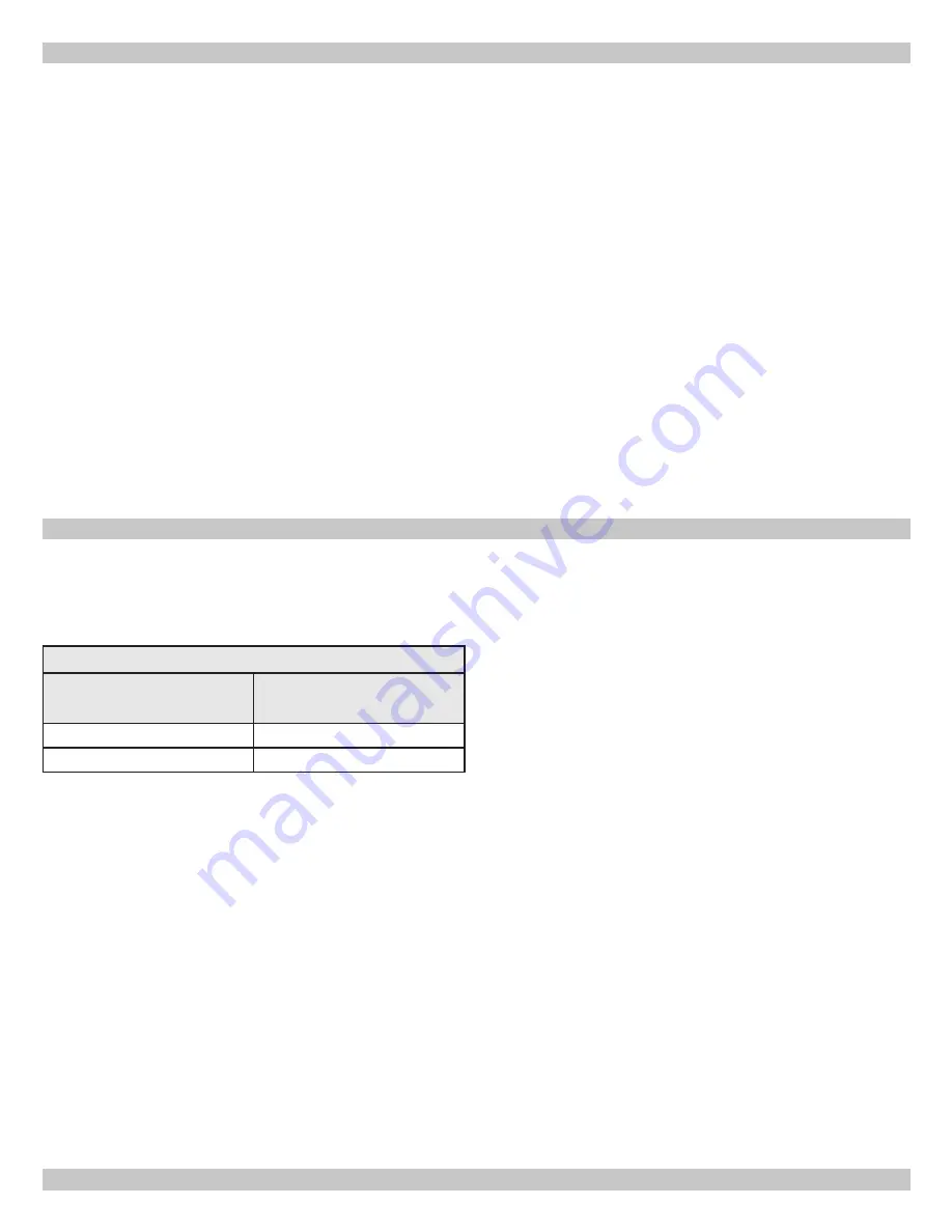
Table 3 - Field Controls

Number Of

Boiler Sections

Field Controls

Power Venter

2, 3, 4, 5

SWG-4D

6, 7

SWG-5D

Some possible reasons for using a power venter for 
sidewall venting: 

1. 

May be preferred by local codes.

2. 

Need a vent piping run beyond 30’ (9.1m) (but not 

more than 50’ (15.2m)).

3. 

The boiler installation site experiences gusting or high 

winds. A power venter can help prevent the boiler from 

short cycling due to gusting or high winds by providing 

vent exhaust pressures greater than the boiler’s 

induced draft blower alone.

4. 

When installers or homeowners prefer a negative 

pressure vent system instead of a positive pressure 

vent system.

5. 

May be more cost effective than stainless steel 
venting, particularly at longer vent length.


The Field Controls power vent kit includes either a 

SWG-II-4HD or SWG-II-5 power venter, a MG-1 4” 
barometric draft controller, and the CK-43D controls kit.

Confirm that installing a power venter is an option allowed 

by local codes. Follow the specific power venter installation 

instructions issued with the power venter kits. Although 

the power venter is equipped with its own fan, the fan on 

the boiler remains in place and is unaltered when a power 

venter is used. 
When sidewall venting, flue gases must be vented to a 

point in relation to the prevailing wind so that they may 

freely disperse without being blown back at the building 

causing discoloration, or into the building through doors or 

windows causing odors. Also, under certain conditions flue 

gases will condense, forming moisture. In such cases, steps 

should be taken to prevent building materials at the vent 

terminal from being damaged by the exhausted flue gas.
When installing single wall galvanized vent pipe for power 

venting follow the specific power venter installation 

instructions for layout, location of the barometric draft 

control and termination connections. 
When joining and sealing the single wall galvanized or Type 

B vent piping, use RTV silicone sealant with a minimum 

temperature rating of 400°F. For 3” vent pipe runs, be

-

gin with the female end of the vent pipe over the boiler’s 

induced draft blower outlet. For 4” vent pipe runs begin 

with the galvanized 3” to 4” increaser fitting (included in 

the boiler’s parts bag) over the induced draft blower outlet. 

Then follow by placing the female end of the 4” vent pipe 

over the increaser fitting. 
When joining pieces of single wall galvanized vent pipe, a 

substantial bead of silicone should be used at the joint to 

insure a leak proof connection.

Summary of Contents for Olsen OSVB II Series

Page 1: ...rs INSTALLATION OPERATION MAINTENANCE MANUAL Manufactured by ECR International Inc 2201 Dwyer Avenue Utica NY 13501 web site www ecrinternational com Models OSVB 2 OSVB 3 OSVB 4 OSVB 5 OSVB 6 OSVB 7 A...

Page 2: ...ch if not avoided could result in minor or moderate injury WARNING Indicates a hazardous situation which if not avoided could result in death or serious injury DANGER Indicates a hazardous situation w...

Page 3: ...use with Natural and Propane Gases Constructed and hydrostatically tested for maximum working pressure of 50 psi in accordance with A S M E Boiler and Pressure Vessel Code Section IV Standards for ca...

Page 4: ...4 DIMENSIONS Model Width A OSVB 2 11 OSVB 3 14 1 4 OSVB 4 17 1 2 OSVB 5 20 3 4 OSVB 6 24 OSVB 7 27 1 4...

Page 5: ...h respect to heat distribution system as practical 7 Verify you have the right size boiler before starting installation See rating and capacity table 8 When installed in utility room door should be wi...

Page 6: ...communicating directly or by ducts with outdoors Two Permanent Opening Method Provide opening commencing within 12 inches of top and second opening commencing within 12 inches of bottom enclosure Dire...

Page 7: ...ve See Figure 2 Use or larger pipe Use pipe suitable for temperatures of 375 F 191 C or greater Individual boiler discharge piping shall be independent of other discharge piping Size and arrange disch...

Page 8: ...HEIGHT FOR LOW WATER CUTOFF PROBE Figure 3 Forced Hot Water Typical Piping LIMIT SENSOR MINIMUM HEIGHT FOR LOW WATER CUTOFF PROBE Figure 4 Forced Hot Water Typical Piping With Zone Control Valve INST...

Page 9: ...5 Boiler connected to heating coils located in air handling units exposed to refrigerated air circulation piping system shall be equipped with flow control valves or other automatic means to prevent...

Page 10: ...stem 6 Vent connector from boiler to chimney should run as directly as possible with as few elbows as possible 7 Where possible it is recommended to common vent water heater and boiler Consult appropr...

Page 11: ...s of the apex Boiler Water Heater Chimney CHECK YOUR CHIMNEY For boilers for connection to gas vents or chimneys vent installations shall be in accordance with Venting of Equipment of the National Fue...

Page 12: ...m exhausts so they will operate at maximum speed Do not operate a summer exhaust fan Close fireplace dampers 4 Place in operation the appliance being inspected Follow the lighting instructions Adjust...

Page 13: ...eter 90 elbow or 3 feet of straight pipe for 3 diameter 90 elbow 2 3 4 5 Section Boilers use 3 vent pipe for 6 7 Section Boilers use 4 vent pipe CHOICE OF VENT PIPE MATERIAL U L Listed Z Flex Z Vent S...

Page 14: ...er A A 90 elbow pointing down fitted with a minimum 1 4 mesh screen to keep out rodents and birds The elbow shall be of the same material and size as vent pipe The elbow exit should be at least 6 away...

Page 15: ...ained from electric meters gas meters regulators and relief equipment See Figure 9 HORIZONTAL VENTING INSTRUCTIONS Figure 9 Horizontal Venting Clearances Canada Terminate vent system at least 6 feet 1...

Page 16: ...before operating appliance B For Heat Fab Saf T Vent stainless steel vent pipe use a high temperature silicone sealant rated for 550 F The outside of the male end and inside of the female end of the p...

Page 17: ...om the boiler to prevent collection of condensate throughout the assembly 7 Allow the sealant to cure for 24 hours before operating the appliance D For ProTech Systems FasNSeal stainless steel vent pi...

Page 18: ...trols Power Venter 2 3 4 5 SWG 4D 6 7 SWG 5D Some possible reasons for using a power venter for sidewall venting 1 May be preferred by local codes 2 Need a vent piping run beyond 30 9 1m but not more...

Page 19: ...wo pipe wrenches when making connection to gas valve to keep it from turning Install manual shut off valve in vertical pipe about 5 feet 1 5m above floor See Figure 10 Tighten all joints securely Prop...

Page 20: ...pacity BTU Per Hour Input Includes Fittings 1 1 20 92 000 190 000 350 000 625 000 40 63 000 130 000 245 000 445 000 60 50 000 105 000 195 000 365 000 Table 6 PROPANE GAS Length of Pipe Ft Pipe Capacit...

Page 21: ...ve the floor 2 NEVER install a thermostat on an outside wall 3 Do not install a thermostat where it will be affected by drafts hot or cold pipes sunlight lighting fixtures televisions a fireplace or a...

Page 22: ...water temperature reaches high limit set point high limit contacts open cutting power to blower and pilot control Burners extinguish and blower stops Circulator pump continues to run as long as the t...

Page 23: ...23 WIRING DIAGRAMS Figure 12 Control Module Damper is not an option...

Page 24: ...s Repeat until you have covered every radiation unit in system End at highest unit in system If units have automatic vents manual venting is unnecessary but it will speed up proper filling of system I...

Page 25: ...ob WARNING If you do not follow these instructions exactly a fire or explosion may result causing property damage personal injury or loss of life This appliance is equipped with an ignition device whi...

Page 26: ...justment and are not equipped with primary air shutters Main burner flames form sharp blue inner cones in softer blue outer mantel with no yellow Puffs of air from blow ing on flame or stamping on flo...

Page 27: ...supply to burners 3 Turn your thermostat up to call for heat and let your boiler run until temperature of water reaches limit setting Gas valve shuts off and circulator keeps running until thermostat...

Page 28: ...eft in to freeze will crack pipes and or boiler Cleaning Your Boiler And Burners Flue passages between sections should be examined yearly and cleaned if necessary To clean Remove burners pilot and ven...

Page 29: ...ctrical contact Check all control terminals and wire joints Chimney flue is blocked Pressure switch will not close and pilot spark will not operate to start pilot Have your service technician check an...

Page 30: ...as temperature changes Diaphragm type tank can be mounted on air purger fitting or at any convenient place in supply or return line AIR ELIMINATING FITTING AIR PURGER Air purger is used to remove exc...

Page 31: ...ed Factory Pressure Switch Set point 0 4 wc for 2 5 section boilers 0 5 w c for 6 7 section boilers ROLLOUT SWITCH FLAME ROLLOUT SAFETY SHUTOFF Rollout switch is temperature sensitive fuse link device...

Page 32: ...using wire nuts Ensure remaining Molex plug connectors have not worked loose during transit Check sensing bulb is fully inserted in well and is not loose A 3 Adjusting Settings To discourage unauthori...

Page 33: ...ion was not detected and delay is called before retry Recycle delay Flame signal was lost and delay is called before retry 11 Wait for pressure switch to open failed to close Inducer is still off Pres...

Page 34: ...out models must be reset through key buttons and display On retry models wait for retry or reset at thermostat Check for correct installation and wiring before replacing any component Control module c...

Page 35: ...out Soft lockout is reset after one hour if alarm reason disappears 63 Soft lockout maximum number of recycles exceeded Soft lockout 64 Soft Lockout electronics failure On board self diagnostics detec...

Page 36: ...lace damaged wire Check for cracked ceramic insulator which can cause short to ground and replace igniter sensor if necessary At gas valve disconnect main valve wire from MV terminal Turn on power and...

Page 37: ...NOTES...

Page 38: ...38 NOTES...

Page 39: ...39 Company Address Phone Company Name Tech Initials Service Performed Date SERVICE RECORD...

Page 40: ...ECR International 2201 Dwyer Avenue Utica NY 13501 web site www ecrinternational com...

Reviews: