background image

ECOWATER

S Y S T E

M S

Installation

11

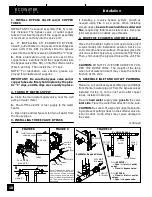
6. CONNECT INLET AND OUTLET PLUMBING

Complete the inlet and outlet plumbing as applica-

ble, below.

a.

SOLDERED COPPER

(1) Thoroughly clean and flux all joints.

(2) Pull the plastic ‘‘C’’clips and remove the inlet and

outlet tubes from the valve. Remove o--rings from

the tubes.

DO NOT solder with tubes in the valve.

Soldering heat will damage the valve.

NOTE

: If installing a ground as shown in figure 8A,

place hose clamps on copper tubes before sol-

dering

(see step 7a).

(3) Make all solder connections. Be sure to keep fit-

tings fully together, and pipes square and straight.

IMPORTANT: Be sure the bypass valve and/or

copper tubes are firmly held in place by the plas-

tic ‘‘C’’clips, and the clips are securely in place.

b.

THREADED PIPE

(1) Apply pipe joint compound to all outside pipe

threads.

(2) Tighten all threaded joints.

(3) If soldering to the inlet and outlet tubes, observe

steps

a

above.

c.

CPVC PLASTIC PIPE

(1) Clean, prime and cement all joints, following the

manufactures instructions supplied with the plastic

pipe and fittings.

(2) If soldering to the inlet and outlet tubes, observe

step

a

above.

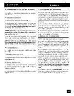
7. COLD WATER PIPE GROUNDING

The house cold water pipe (metal only) is often used

as a ground for the house electrical system. The

3-valve bypass type of installation, shown in FIG. 3,

will maintain ground continuity. If you use the plastic

bypass valve at the Eco System Unit, continuity is

broken. To restore the ground, do either step

a

or

b

following.

a.

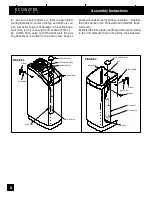
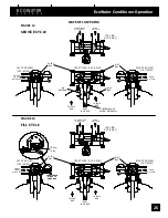
Use the included hose clamps and wire, to make

a jumper across the inlet and outlet copper tubes,

FIG. 8A. Put hose clamps on the copper tubes be-

fore soldering, step 6a.

b.

Install a #4 copper wire across the removed sec-

tion of main water pipe, securely clamping at both

ends, FIG. 8B (parts not included).

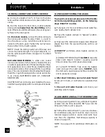
8. INSTALL VALVE DRAIN HOSE

NOTE: See valve drain options on page 8.

a.

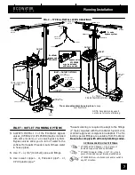
Connect a length of 1/2”I.D. hose (check codes)

to the valve drain elbow, on the controller, FIG. 5.

Use a hose clamp to hold the hose in place. Route

the hose out through the notch in the back of the top

cover.

b.

Run the hose to the floor drain, and as typically

shown in FIG. 4, tie or wire the end to a brick or other

heavy object. This will prevent ‘‘whipping’’during re-

generations. Be sure to provide a 1--1/2”minimum

air gap, to prevent possible sewer water backup.
NOTE: In addition to a floor drain, you can use a

laundry tub, sump, or standpipe as a good drain

point for this hose. Avoid long drain hose runs, or

elevating the hose more than 8’above the floor.

If

using a sump drain, be sure it does not dis-

charge on a surface that salty water could dam-

age.

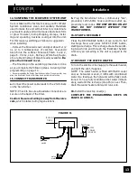
9.

IF INSTALLING A

2--TANK MODEL,

move the

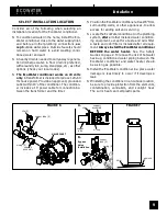
brine tank into position next to the resin tank. Ob-

serve the instructions in step 4, page 10.

Summary of Contents for ES9120R

Page 1: ...t No 7214749 1 2000 EcoWater Systems PO Box 64420 St Paul MN 55164 9888 OWNERS MANUAL how to maintain and operate your EcoWater digital demand water system MODELS ES9120R ES9120RP ES9130R ES9230R ES9230RP ES9240R ES9270R ...

Page 2: ...need to make the installation Check local plumbing and electrical codes The installation must conform to them Use only lead free solder and flux for all sweat solder connections as required by state and federal codes Use care when handling the EcoWater Systems conditioner Do not turn upside down drop or set on sharp protrusions Do not locate the EcoWater Systems conditioner where freezing temperat...

Page 3: ...R THESE WARRANTIES IS TO REPLACEOR REPAIRTHE COMPONENTOR PARTWHICH PROVES TO BE DEFECTIVE WITHIN THE SPECIFIED TIME PERIOD AND ECOWATER IS NOT LIABLE FOR CONSE QUENTIAL OR INCIDENTAL DAMAGES NO ECOWATER DEALER AGENT REPRESENTATIVE OR OTHER PER SON IS AUTHORIZED TO EXTEND OR EXPAND THE WARRANTIES EXPRESSLY DESCRIBED ABOVE Some states do not allow limitations on how long an implied warranty lasts or...

Page 4: ...in tablets Water hardness varies greatly across the country It generally contains from 3 to 100 gpg Hard water affects living in general Hardnessminer als combine with soap to make a soap curd The curd greatly reduces the cleaning action of soap Precipitated hardness minerals form a crust on cooking utensils appliances and plumbing fixtures Even the tastes of foods are affected A water soft ener r...

Page 5: ...other beverages 3 ACIDITY or acid water is caused by carbon diox ide hydrogen sulfide and sometimes industrial wastes It is corrosive to plumbing plumbing fix tures water heaters and other water using ap pliances In can also damage and cause premature failure of seals diaphragms etc in water handling equipment A chemical analysis is needed to measure the de gree of acidity in water This is called ...

Page 6: ...l Be sure the float stem is vertical to the brine valve body so seals will seat properly during operation Replace the brine valve in the brinewell and install the brine well cover 3 Install the brine tank overflow grommet and elbow in the 3 4 diameter hole in the brine tank sidewall grommet elbow nozzle assembly brine tubing brine tank brinewell brine valve screw slots brine valve brinewell brine ...

Page 7: ...TER bypass valve 7195408 may be included with some models INLET OUTLET PLUMBING OPTIONS S ALWAYS INSTALL 1 of the EcoWater bypass valves 7083122 or 7195408 may be included with some models or a 3 valve bypass system Bypass valves allow you to turn of water to the softener for repairs if needed but still have water in house pipes S Use 1 or 3 4 minimum pipe and fittings S Use sweat copper or thread...

Page 8: ...m pound D solvent cement D emery cloth sandpaper or steel wool D primer MATERIALS YOU MAY NEED H bypass valve or 3 valves H pipe and fittings as required H1 2 I D high quality flexible hose for the valve drain and brine tank drain The brine tank drain el bow accepts either 1 2 or 3 8 I D hose VALVE DRAIN OPTIONS Flexible drain hose isnot allowed in all localities check your codes To make a rigid v...

Page 9: ...the timer S Position the EcoWater conditioner at least 6 from surrounding walls or other appliances to allow access for adding salt and servicing S Locate the EcoWater conditioner in the plumbing system after all other installed water condition ing equipment except for a taste and odor filter A taste and odor filter is installed after all equip ment Always install the EcoWater conditioner BEFORE t...

Page 10: ... the EcoWater System Unit resin tank only if 2 tank model into installation position Set it on a solid smooth and level surface If needed place the unit on a section of plywood a minimum of 3 4 thick Then shim under the plywood to level the unit FIG 7 CAUTION DO NOT PLACE SHIMS DIRECTLY UN DER THE BRINE TANK The weight of the tank when full of water and salt may cause the tank to fracture at the s...

Page 11: ...ypass type of installation shown in FIG 3 will maintain ground continuity If you use the plastic bypass valve at the Eco System Unit continuity is broken To restore the ground do either step a or b following a Use the included hose clamps and wire to make a jumper across the inlet and outlet copper tubes FIG 8A Put hose clamps on the copper tubes be fore soldering step 6a b Install a 4 copper wire...

Page 12: ...hold the housing tightly with 1 hand to prevent break age 12 PRESSURE TESTING FOR LEAKS To prevent excessive air pressure in the EcoWa ter Unit and plumbing system do the following steps EXACTLY in order a Fully open 2 or more conditioned cold water fau cets nearby the EcoWater Unit b Place the bypass valve s in bypass position See figure 10 c Fully open the main water supply valve Observe steady ...

Page 13: ...rminals on the transformer NOTE Check to be sure all leadwire connectors are secure on the back of the timer Caution Be sure all wiring is away from the valve cam which rotates during regenerations b Plug the transformer into a continuously live grounded 120V 60Hz house electrical outlet ap proved by local codes THE UNIT WORKS ON 24V ONLY DO NOT CONNECT WITHOUT THE TRANSFORMER 16 START A RECHARGE ...

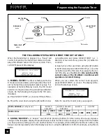
Page 14: ...ow press the button to continue c Again move the cusor down using the button to Set Model and press SELECT EXIT Use the button to set the HR code If you pass by the cor rect HR code use the button Be sure to set the correct code or the EcoWater conditioner will operate on incorrect timing When you are certain the correct code appears press SELECT EXIT to set The display will re turn to the start u...

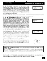
Page 15: ...e hardness level and exit to the primary menu 4 SET RECHARGE REGENERATION TIME Press SELECT EXIT to enter Primary Menu Move the cursor so that it is next to Set Recharge Time Press the SELECT EXIT button once to display a flashing 2 00 AM At this setting the EcoWater conditioner begins recharge or regeneration at 2 00 AM ending no later than 5 30 AM This is a good time in most households because w...

Page 16: ...city before the next recharge is automatically initiated To be sure this will not happen use RECHARGE NOW to restore 100 condi tioned water capacity RECHARGE TONIGHT Press the Recharge button to go to the recharge menu Move cursor down to Set Cancel Recharge Tonight Press SELECT EXIT button to return to Normal Screen Views When this feature is set the EcoWater conditioner will regenerate at the ne...

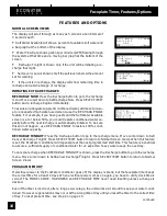
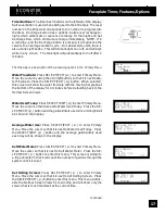
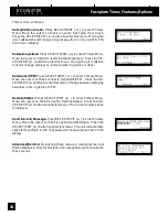
Page 17: ...en selected this screen will show the water flow rate with the moving bar graph at the bottom of the display for 4 minutes before defaulting back to the Normal Screen Views Water Used Today PressSELECT EXIT to enter PrimaryMenu Move the cursor so that it is next to Water Used Today Press the SE LECT EXIT button and the gallons liters used since midnight will be shown in the display Average Water U...

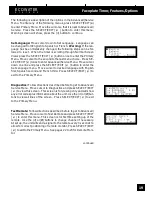
Page 18: ...PM Press SELECT EXIT to enter Primary Menu Move the cursor so that it is next to Set Grains PPM Press the SE LECT EXIT button to enter this menu Change between diplaying hardness units in grains or PPM Remote Status Press SELECT EXIT to enter Primary Menu Move the cursor so that it is next to Remote Status Press the SE LECT EXIT button to enter this menu The current remote status is diplayed Send ...

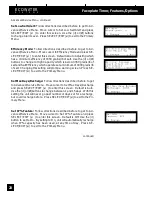
Page 19: ...n one line and press the SELECT EXIT button to enter the Set Language menu Move cursor to desired language with English first Spanish second and French third Press SELECT EXIT to exit to the Primary Menu Diagnostics Follow directions described before to get to Advanced Service Menu Move cursor to Diagnostics and press SELECT EXIT to view this screen This screen is for viewing only and will show an...

Page 20: ...ch operates at a minimum of 4000 grains lb of salt Changing this setting will promp a warning screen Press SE LECT EXIT to exit to the Primary Menu Set Max Days Recharge Follow directions described before to get to Advanced Service Menu Move cursor to Set Max Days Recharge and press SELECT EXIT to enter this screen Default is Auto Use the or buttons to change between 1 and 15 days With this settin...

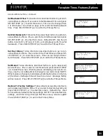
Page 21: ...ove cursor to Set Fast Rinse and press SE LECT EXIT to enter this screen Time can be changed from 1 to 30 minutes Press SELECT EXIT to exit to the Primary Menu Set Model Follow directions described before to get to Advanced Service Menu Move cursor to Set Model and press SELECT EXIT to enter this screen Warning screen will display press to con tinue Use the or buttons to change to new model code N...

Page 22: ... to be repositioned Press SELECT EXIT to exit to the Primary Menu Now the unit should start transmitting a normal signal The timer on the EcoWater Systems conditioner will send a signal to the remote monitor every minute The remote monitor will listen for a signal every 10 minutes Any changes in softener status could possibly take up to 10 minutes before the remote registers the change If the unit...

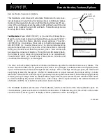
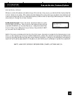
Page 23: ...ed before to get to Advanced Service Menu Move cursor to Set Remote Channel and press SELECT EXIT to enter this screen Default is random from 1 to 16 Press or to select new channel PressSELECT EXIT to exit to the Primary Menu NOTE This device complies with Part 15 of the FCC Rules Operation is subject to the following two condi tions 1 this device may not cause harmful interference and 2 this devi...

Page 24: ... resin looks somewhat like coarse sand but the beads are round and smooth Resin has the ability to remove hard ness minerals from water by ion exchange SERVICE FIG 14 Hard water enters the EcoWater conditioner passes through the valve and down into the resin tank and resin bed As it passes through the bed hardness minerals are extracted from the water and held by the resin beads Conditioned water ...

Page 25: ...istributor HARD WATER IN CONDI TIONED WATER OUT FIGURE 14 SERVICE CYCLE FRONT VIEW CUT AWAY TOP VIEW CUT AWAY HARD WATER IN CONDITIONED WATER OUT LEFT END VIEW CUT AWAY RIGHT END VIEW CUT AWAY outlet disc inlet disc to resin bed to resin bed from resin bed CONDI TIONED WATER OUT FIGURE 15 FILL CYCLE HARD WATER IN CONDITIONED WATER TO BRINE TANK fill flow plug ECOWATER S Y S T E M S EcoWater Condit...

Page 26: ...ve float seats to prevent air induction Water con tinues to flow in the same direction except for the dis continued brine flow Hardness minerals and brine rinse from the resin bed and flow to the drain Brining and brine rinse time is also variable and con trolled by the timer see page 33 BYPASS HARD WATER During brining and brine rinse also backwash and fast rinse page 27 hard water is bypassed th...

Page 27: ...eration 27 FIGURE 17 STEP 4 BACKWASH The motor drives the valve to end brine rinse and begin backwash In backwash a fast upward flow of water through the resin bed flushes remaining hardness minerals brine dirt sediments iron deposits etc from the bed and to the drain The fast flow lifts and expands the resin bed for maxi mum cleaning STEP 5 FAST RINSE After backwash valve rotation places the valv...

Page 28: ...u will have hard water If the brine tank is full of salt it is hard to tell if you have a salt bridge Salt is loose on top but the bridge is under it Take a broom handle or like tool and push it straight down into the salt If a hard object is felt it s most likely a salt bridge Carefully push into the bridge in several places to break it NOTE In humid areas it is best to keep the salt stor age lev...

Page 29: ...N TANK SIZE FREE BOARD RANGE LBS RESIN PER INCH BED DEPTH ES9120R 8 x 35 8 5 12 5 1 6 ES9120RP ES9130R ES9230R 10 x 35 10 5 14 5 2 2 ES9230RP ES9240R 10 x 47 14 5 18 5 2 2 ES9270R 12 x 54 20 24 3 4 does not include carbon in plus models Freeboard range and lbs of resin per inch bed depth in the preceding chart are provided only as a guide for maintenance when adding to or if replac ing the entire ...

Page 30: ...he correct time of day If display is blank check power source to the Eco Water conditioner If time is incorrect power was off for over 2 days The conditioner resumes normal operation when power returns but regenerations occur at the wrong time If an error code shows in the display example Er ror 3 go to AUTOMATIC ELECTRONIC DIAGNOS TICS following 2 Are plumbing bypass valve s in service position a...

Page 31: ...ICS 1 To enter diagnostics press the SELECT EXIT to enter the menu This screen contains informa tion that can be used to troubleshoot errors Use the and buttons to scroll through all lines on this screen The first line shows time of day and error code Second line is Pos which shows what position the valve is in Example Service Fill Brining and Brine Rinse Backwash and Fast Rinse The clock to the r...

Page 32: ...IT to start a recharge As the EcoWater conditioner enters the fill cycle of regeneration remove the brinewell cover and using a flashlight observe fill water enter ing the tank a If water does not enter the tank look for an ob structed nozzle and venturi fill flow plug or brine tub ing FIG 19 page 28 2 After verifying fill press Recharge to move the valve into brining A slow flow of water to the d...

Page 33: ...46 3 R70 100 6 R20 Plus models use 33 7 lbs resin 9 6 lbs of carbon and 10 lbs gravel R30 Plus models also have 12 lbs of carbon OTHER SERVICE HARD WATER BYPASS hard water bleeds into conditioned water supply 1 Defective inlet disc seal or wave washer see pages 38 and 39 2 Missing or defective o ring s at resin tank to valve connection standpipe top distributor resin tank valve assembly shipping c...

Page 34: ...14 before changing this code 1 Press SELECT EXIT to enter Primary Menu 2 Move the cursor next to Advanced Service Press the SELECT EXIT button to enter this menu 3 Warning screen will show press the button to continue 4 Use the or buttons to change to new model code 5 Reset the timer pages 14 15 and reselect other desired options FOR FUTURE REFERENCE ENTER THE FOLLOWING INFORMATION MODEL NO ÀÁ DAT...

Page 35: ...Capa ciy Resin cu ft Water Supply Max Hardness gpg Water Supply Max Clear Water Iron ppm Water Pressure Limits min max psi 20 125 Max Water Tempera ture F 120 Min Water Supply Flow Rate gpm 3 Max Drain Flow Rate gpm MODEL NOMINAL RESIN TANK SIZE A B C R20 8 DIA X 35 35 39 5 43 R30 R20 Plus 10 DIA X 35 35 39 5 43 R40 R30 Plus 10 DIA X 47 47 51 3 55 R70 12 DIA X 54 53 57 3 61 SALT STORAGE CAPACITIES...

Page 36: ...S T E M S Repair Parts 36 ECOWATER CONDITIONER ASSEMBLY 9 8 10 11 33 34 35 36 37 38 39 12 13 14 15 16 17 20 21 30 26 25 23 24 23 24 32 22 19 20 21 31 40 42 43 44 15 47 45 25 1 2 3 4 5 7 48 41 6 28 29 46 27 18 19 22 ...

Page 37: ... Brinewell Cover 21 7109871 Brinewell 7214236 Decal Salt Level 22 7214935 Screw 1 4 20 23 9003500 Grommet 24 1103200 Hose Adaptor 0900431 Hose Clamp not shown 25 7141205 Tank Base 26 x Brine Tank tank in tank 27 x Light Assembly includes o ring and nut KEY NO PART NUMBER PART DESCRIPTION 28 7210397 Rim tank in tank 29 7214244 Vapor Barrier 30 7210389 Salt Hole Cover 31 7210486 Brine Tank Cover 32 ...

Page 38: ...OWATER S Y S T E M S Repair Parts 38 1 2 3 4 5 6 7 8 9 10 11 12 13 14 15 16 17 18 19 15 20 21 22 23 24 25 26 27 28 29 30 31 32 33 34 35 36 37 38 12 39 13 40 41 42 43 44 45 46 47 48 49 50 VALVE ASSEMBLY 11 ...

Page 39: ...nt wht Gasket Kit 9120R x Nozz Vent blk Gasket Kit 9120RP 9130R 9230RP 9230R 9240R x Nozz Vent blu Gasket Kit 9270R 7204362 Gasket Black only 26 1148800 Fill Flow Plug 3 KEY NO PART NUMBER PART DESCRIPTION 27 7085221 Noz Ven Assy 9120R 7091866 Nozz Vent Assem 9120RP 9130R 9230RP 9230R 9240R 7085247 Nozz Vent Assem 9270R 28 0521829 Flow Plug 1 9120R 29 7095030 Cone Screen 30 7003847 O ring 1 4 x 1 ...

Page 40: ...ECOWATER S Y S T E M S 3 EcoWater Systems PO Box 64420 St Paul MN 55164 9888 ...

Reviews: