background image


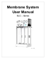
ELC 

– Series User Manual 

          MKTF 

– 506-A 

10 

03/18


MEMBRANE ELEMENTS 

ELC 

– Series Reverse Osmosis Systems are equipped with Thin Film Composite (TFC) HF5 

– Ultra Low Energy membranes, unless otherwise specified. General membrane element 
performance characteristics are listed below. 

HF5 

– Ultra Low Energy Membranes 


Membrane Type

: Polyamide Thin 

– Film Composite 


pH Range, Short Term Cleaning (30 Min.)

: 1 

– 13


Maximum Operating Temperature

: 113°F


Maximum Feed Silt Density Index (SDI)

: 5


Maximum Operating Pressure

: 400 psi


Chlorine Tolerance

: 0 ppm


pH Range, Continuous Operation*

:


– 11


Maximum Feed Flow Rate (gpm)

: 2.5” = 6; 4.0” = 16


*Maximum temperature for continuous operations above pH10 is 95°F (35°C). 
 

Product Specifications


Part Number 

Description 

Applied  

Pressure (psi)  

Permeate Flow  

Rate (gpd) 

Nominal Salt  

Rejection (%) 

209175 

HF5 

– 3018 

80 

750 

98.5% 


Warranty Evaluation Test Conditions: 

Permeate flow and salt rejection based on the following test conditions 

– 550 ppm, filtered and dechlorinated municipal tap water, 77°F / 25°C, 15% recovery 

and the specified operating pressure. Minimum salt rejection is 96%. Permeate flows for warranty evaluation may vary +/-20%. Maximum pressure drops at 13 psi / 0.9 bar. 


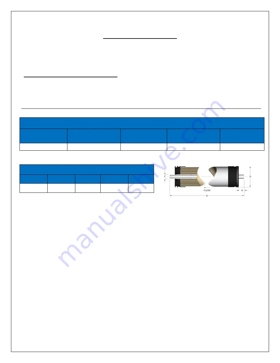
Dimensions inch / mm


Description 

HF5 

– 3018 

19.75 

0.98 

0.745 

3.00 


Proper start

–up of reverse osmosis water treatment systems is essential to prepare the membranes for operating service and to prevent membrane damage due to 

overfeeding or hydraulic shock. Before initiating system start

–up procedures, membrane pretreatment, loading of the membrane elements, instrument calibration 

and other system checks should be completed. 
 
Avoid any abrupt pressure or cross

–flow variations on the spiral elements during start–up, shutdown, cleaning or other sequences to prevent possible membrane 

damage. During start

–up, a gradual change from a standstill to operating state is recommended as follows: 


Feed pressure should be increased gradually over a 30 

– 60 second time frame.  


Cross

–flow velocity at set operating point should be achieved gradually over 15 – 20 seconds. 


Permeate obtained from first hour of operation should be discarded. 


Maximum pressure drops across an entire pressure vessel (housing) is 30 psi / 2.1 bar. 


Avoid static permeate

–side backpressure at all times. 

 
Under certain conditions, the presence of free chlorine, chloramines and other oxidizing agents will cause premature membrane failure. Since oxidation damage is 
not covered under warranty, the manufacturer recommends removing all oxidizing agents by pretreatment prior to membrane exposure. Please contact the 
manufacturer or your supplier for more information. 
 
Do not use this initial permeate for drinking water or food preparation. Keep elements moist at all times after initial wetting. To prevent biological growth during 
prolonged system shutdowns, it is recommended that membrane elements be immersed in a preservative solution. Rinse out the preservative before use. For 
membrane warranty details, please contact the manufacturer or your supplier for more information. 
 
If operating limits and guidelines given in this product specification sheet are not strictly followed, the warranty will be null and void. The customer is fully responsible 
for the effects of incompatible chemicals and lubricants on elements. Use of any such chemicals or lubricants will void the warranty. These membranes may be 
subject to drinking water application restrictions in some countries: please check the application status before use and sale. The use of this product in and of itself 
does not necessarily guarantee the removal of cysts and pathogens from water. Effective cyst and pathogen reduction is dependent on the complete system design 
and on the operation and maintenance of the system. 
 
No freedom from infringement of any patent owned by the manufacturer or others is to be inferred. Because use conditions and applicable laws may differ from one 
location to another and may change with time, customer is responsible for determining whether products and the information in this document are appropriate for 
customer’s use and for ensuring that customer’s workplace and disposal practices are in compliance with applicable laws and other governmental enactments. The 
claims made may not have been approved for use in all countries. The manufacturer assumes no obligation or liability for the information in this document. NO 
WARRANTIES ARE GIVEN; ALL IMPLIED WARRANTIES OF MERCHANTABILITY OR FITNESS FOR A PARTICULAR PURPOSE ARE EXPRESSLY 
EXCLUDED.


Summary of Contents for ELC-1500

Page 1: ...Membrane System User Manual ELC Series ELC 1500 w...

Page 2: ...ELC Series User Manual MKTF 506 A 2 03 18 This page intentionally left blank...

Page 3: ...ICATION 11 MEMBRANE INSTALLATION REMOVAL AND REPLACEMENT 13 INITIAL START UP 17 OPERATING DO S AND DON TS 18 RO SHUT DOWN PROCEDURE 18 PRODUCT SPECIFICATIONS 19 OPERATING LIMITS 20 OPERATION AND MAINT...

Page 4: ...of operation or if the feedwater conditions change please contact your local dealer or distributor to determine the proper recovery for your application IN ORDER TO MAINTAIN THE MANUFACTURER S WARRANT...

Page 5: ...Y CAUTION WARNING OR OTHER DESCRIPTIVE LABELS FROM THE SYSTEM PLEASE READ THE ENTIRE MANUAL BEFORE PROCEEDING WITH THE INSTALLATION AND START UP FAILURE TO FOLLOW INSTRUCTIONS OR OPERATING PARAMETERS...

Page 6: ...WARRANTY OPERATING LIMITS Operating Parameters Feed Temperature 40 85 F System Inlet Pressure 40 60 psi Maximum Operating Pressure at 77 F 90 psi Feedwater Requirements Maximum SDI Rating 3 Maximum Tu...

Page 7: ...ot pass through the membrane To calculate the percentage of rejection use the following formula Rejection Feed TDS Product TDS Feed TDS x 100 Example 98 5 550 8 25 550 x 100 ALL TDS FIGURES MUST BE EX...

Page 8: ...ed storage tank locate the 3 8 quick connect tubing fitting labeled holding tank on the right side of the frame Attach 3 8 tubing and connect it to the pressurized storage tank Ensure that the permeat...

Page 9: ...tch turns the system on when the water level in the tank drops and off when the tank is full Should you choose a liquid switch s for your application it can be obtained by your local dealer or distrib...

Page 10: ...re vessel housing is 30 psi 2 1 bar Avoid static permeate side backpressure at all times Under certain conditions the presence of free chlorine chloramines and other oxidizing agents will cause premat...

Page 11: ...ELC Series User Manual MKTF 506 A 11 03 18 SYSTEM IDENTIFICATION Figure 1...

Page 12: ...INLINE DM 2 1 2 QC HM DIGITAL 203385 750 1500 9 GAUGE PM GLY FILL 0 100 PSI BAR 2 5 DIA 1 4 MNPT AXEON 204165 750 1500 10 VALVE SOLENOID N C UL 110V 1 2 FNPT 3 METER CORD GC 204909 750 1500 11 METER F...

Page 13: ...OM THE SYSTEM 1 Disconnect the tubing from the bottom of the membrane housing Unscrew the membrane from the system 2 Remove the replacement membrane element s from the shipping box the membrane s shou...

Page 14: ...old membrane element out of the membrane element housing 3 Lubricate the brine seal and o rings with a non petroleum based lubricant such as Dow Corning 111 Do not use a petroleum based lubricant 4 In...

Page 15: ...ELC Series User Manual MKTF 506 A 15 03 18 Figure 2...

Page 16: ...ELC Series User Manual MKTF 506 A 16 03 18 Figure 3...

Page 17: ...Figure 1 Page 11 2 Fully close the concentrate recycle valve by turning it clockwise 14 Figure 1 Page 11 3 Plug the RO system in and adjust the concentrate waste valve and recycle valve to the design...

Page 18: ...ystem for extended periods Operate the system with insufficient feed flow Operate the pump dry RO SHUT DOWN PROCEDURE 1 Purge system See Initial Start up instructions 2 Turn off feed supply water from...

Page 19: ...e Size 3018 3018 Vessels Vessel Array 1 1 1 Vessel Quantity 1 2 Pumps Pump Type Rotary Vane 401 Low Lead Brass Rotary Vane 601 Low Lead Brass Motor HP 1 3 HP 1 2 HP RPM at 60 HZ 1725 1725 System Elect...

Page 20: ...essure vessel housing is 30 psi 2 1 bar Avoid static permeate side backpressure at all times Under certain conditions the presence of free chlorine chloramines and other oxidizing agents will cause pr...

Page 21: ...ese flow meters indicate the flow rates of the permeate concentrate and recycle water The measurements when added together also indicate the feedwater flow rate or total flow rate EXCESSIVE RECYCLING...

Page 22: ...low these steps 1 The system must be operating during the flush procedure 2 Fully open the concentrate valve by turning it counter clockwise 12 Figure 1 Page 11 3 Allow the system to run for 10 to 20...

Page 23: ...essure vessel being filled For cold weather winter storage add 20 by weight Polyglycol to the 2 M 100 solution Add Polyglycol AFTER the 2 M 100 solution has been mixed 2 Separate the preservation solu...

Page 24: ...er temperature See temperature correction sheet Poor Permeate Quality Low operating pressure See low inlet pressure Damage product tube o rings Inspect and or replace Damaged or oxidized membrane Repl...

Page 25: ...hin 20 of the rated production after correcting the feedwater temperatures above or below 77 F Check the permeate flow meter to determine the permeate flow rate TO DETERMINE THE TEMPERATURE CORRECTION...

Page 26: ...ELC Series User Manual MKTF 506 A 26 03 18 OPERATING LOG...

Page 27: ...RRECTION FACTORS FOR MEMBRANE Find the temperature correction factor TCF from the table below Divide the rated permeate flow at 77 F by the temperature correction factor The result is the permeate flo...

Page 28: ...rection table to obtain the correct flow Example 5 gpm at 59 F 5 1 42 3 52 gpm 5 gpm at 77 F 5 1 5 gpm 5 gpm at 84 F 5 0 89 5 62 gpm SERVICE ASSISTANCE If service assistance is required Contact your l...

Page 29: ...C Series User Manual MKTF 506 A 29 03 18 MODELS ELC 750 ELC 1500 A DIM 36 62 36 62 B DIM 17 20 17 20 C DIM 17 00 17 00 D DIM 15 00 15 00 E DIM 12 00 12 00 F DIM 11 76 11 76 SYSTEM DRAWINGS FLOW DIAGRA...

Page 30: ...ELC Series User Manual MKTF 506 A 30 03 18 ELC 750 FLOW DIAGRAM...

Page 31: ...ELC Series User Manual MKTF 506 A 31 03 18 ELC 1500 FLOW DIAGRAM...

Page 32: ...ELC Series User Manual MKTF 506 A 32 03 18 ELC SERIES ELECTRICAL SCHEMATIC...

Page 33: ...thin three 3 months of shipment from the Manufacturer s manufacturing facility In no event shall the Warranty Commencement Date exceed three 3 months from the shipment from Manufacturer s facility The...

Page 34: ...n and manuals for such product Any expressed Warranty or similar representation of performance set forth in the operation documentation for media or resin incorporated into a product by the Manufactur...

Reviews: