background image

27

ECOWATER

S Y S T E M S

Repair Parts

VALVE ASSEMBLY

Key

No.

Part No.

Description

50

7101548

Turbine Assembly

51

7094898

Turbine Support Assembly

52

7170262

O-Ring, 1.109” x 1.387” (2 req.)

53

7077642

Copper Tube, 1” pipe (2 req.)

54

7234553

Copper Tube, 1-1/4” pipe

(optional) 

55

7089306

Clip Retainer (2 req.) 

56

7276084

Wire Harness w/pos. switch conn.

57

0900060

O-Ring, 3/8” x 1/2”

58

7159949

Disc Valve Housing

59

7078282

Inlet End Seal 

60

7214286

Inlet Disc 

61

7058216

Wave Washer (2 req.)

62

7170220

O-Ring, 3/4” x 15/16” (3 req.) 

63

7170296

O-Ring, 2-7/8” x 3-1/4” (2 req.)

64

7077498

Inlet End Cap

65

7176292

Clamp Section (4 req.) 

66

7142942

Clip, Drain

67

7219066

Drain Nipple

-

7141239

Drain Hose Adaptor (optional) 

Key

No.

Part No.

Description

68

7170327

O-Ring, 5/8” x 13/16”

69

7097969

Flow Plug, Fast Rinse, 3.0 gpm

70

7088033

Retainer, Clamp (4 req.) 

71

7100940

Plug, Aspirator Port

72

7170319

O-Ring, 1/4” x 3/8” (2 req.)

73

7081201

Clip, Nozzle & Venturi

74

7214278

Outlet Disc 

75

7078274

Outlet End Seal 

76

7091329

Driver, Outlet Disc

77

7159965

Outlet End Cap

78

7283497

Cam & Gear

79

7203104

Washerhead Screw, #8-18 x 1/2”

80

7281275

Motor, incl. Key No. 81

81

7289702

Bracket, Motor

82

7168524

Screw, #10-32 x 5/16” (3 req.)

83

7103972

Screw, #8-18 x 7/16” (2 req.)

84

7140738

Screw, #4-24 x 3/4”

85

7145186

Switch

86

7140746

Expansion Pin

Not included

Included in Disc Kit, #7218688

Not all parts are shown

Summary of Contents for ECWS

Page 1: ...N U S A How to install operate and maintain your EcoWater Systems Central Water Filtration System Model ECWS System tested and certified by NSF International against NSF ANSI Standard 42 See performan...

Page 2: ...mum Use a pressure reducing valve if neces sary Adding a pressure reducing valve may reduce the flow The EcoWater Systems Central Water Filter works on 24 volt 60 Hz electrical power only Be sure to u...

Page 3: ...25 000 gal 695 000 gal Backwash Time default length is adjustable 2 minutes Fast Rinse Time default length is adjustable 1 minute Drain Flow Rate during Backwash Fast Rinse 3 0 gpm Amount of Activated...

Page 4: ...er supply inlet and before all other plumbing connec tions except outside water pipes A nearby drain is needed to carry away Clean Rinse discharge water Use a floor drain laundry tub sump standpipe or...

Page 5: ...nnected to a drain TYPICAL INSTALLATION In the state of Massachusetts The Commonwealth of Massachusetts plumbing code 248 CMR shall be adhered to A licensed plumber shall be used for this installation...

Page 6: ...l parts in the bag s until you are ready to use them 2 INSTALL BYPASS VALVE and or COP PER TUBES NOTE Before installing the bypass valve or copper tube into the valve s OUTLET make sure that the tur b...

Page 7: ...the inlet and outlet tubes from the valve Remove o rings from the tubes DO NOT solder with tubes in the valve Soldering heat will damage the valve NOTE If installing a ground as shown in Figure 9 pla...

Page 8: ...ncluded 8 INSTALL VALVE DRAIN HOSE NOTE See valve drain options on Page 5 a Connect a length of 1 2 I D hose check codes to the valve drain elbow on the controller Use a hose clamp to hold the hose in...

Page 9: ...n Page 11 10 CONNECT TRANSFORMER a During installation the Central Water Filtration System wiring may be moved or jostled from place Check to be sure all leadwire connectors are secure on the back of...

Page 10: ...or continued use During the Clean Rinse cycle dirt sediment etc are flushed from the Central Water Filtration System down the drain APPLICATIONS FOR A CENTRAL WATER FILTRATION SYSTEM Do not use the Ce...

Page 11: ...ss and hold the RECHARGE button to initiate the start up cycle The button can be released when you hear the valve changing position and RECHARGE NOW flashes in the display During the start up cycle Th...

Page 12: ...utton to set and change to the flashing PRESENT TIME display SET TIME OF DAY If the words PRESENT TIME do not show in the display press the SELECT button until they do 1 Press the UP or DOWN buttons t...

Page 13: ...correct 3 When the desired Clean Rinse time is displayed press the SELECT but ton a few times until the time appears in the display but is not flashing 12 OR 24 HOUR CLOCK The electronic controller h...

Page 14: ...lay 3 Press the UP or DOWN buttons to set the length of backwash in minutes 4 Press the SELECT button when the desired backwash time is shown SET TIME Fr appears in the display 5 Press the UP or DOWN...

Page 15: ...n has been disabled MANUALLY STARTING A CLEAN RINSE CYCLE To manually start a Clean Rinse cycle 1 If the drain line is not set up to discharge into a drain you must have empty containers ready that wi...

Page 16: ...e lake home etc you must drain all water from it to stop possible freeze damage If the system freezes cracks may develop in plastic parts which will leak causing dam age To drain the unit 1 Close the...

Page 17: ...y initiate a Clean Rinse cycle See Page 13 If the filtration media pores are frequently blocking it may be necessary to increase the frequency of Clean Rinse cycles or add a sediment filter upstream S...

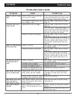
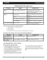
Page 18: ...ak Replace seals and rotor Filter media in house hold plumbing Crack in distributor or riser tube Replace distributor or riser tube Procedure for removing error code from display 1 Unplug transformer...

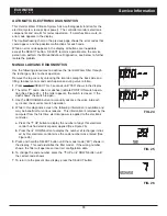
Page 19: ...for 3 seconds until 000 shows in the display 2 The letter P and a dash or dashes indicate POSITION switch opera tion See Figure 24 If the letter appears the switch is closed If the dash shows the swit...

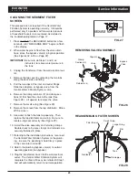
Page 20: ...ners 2 and clamp sec tions 2 that hold the valve to the tank See Figure 28 Lift upward to remove the valve 7 Remove the small o ring See Figure 29 8 Remove the screen from the top distributor Rinse of...

Page 21: ...le on Page 17 1 Remove the clip holding the drain fitting into the valve See Figure 30 2 Remove the drain fitting from the valve 3 Clear any obstruction 4 Reinstall the drain fitting into the valve 5...

Page 22: ...T valve and open the BYPASS valve 4 Close all house faucets PRESSURIZE 1 Open HOT and COLD house faucets 2 Close the BYPASS valve and open the OUTLET valve 3 Slowly open the INLET valve 4 Close all ho...

Page 23: ...23 ECOWATER S Y S T E M S Notes...

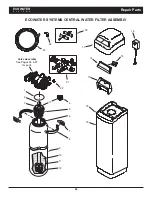
Page 24: ...24 ECOWATER S Y S T E M S Repair Parts ECOWATER SYSTEMS CENTRAL WATER FILTER ASSEMBLY 1 Valve Assembly See Pages 26 27 for parts 2 3 7 4 5 6 8 13 14 9 10 11 19 18 12 15 16 17 21 24 23 20 22...

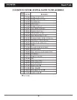
Page 25: ...Section 2 req 9 7304235 Repl Mineral Tank 8 x 35 10 7301619 Activated Carbon 30 lbs 12 lbs req 11 0501783 Filter Sand 10 lbs 5 lbs req 12 7124415 Gravel 17 lbs 6 lbs req 13 7210478 Cover 14 7210509 Fa...

Page 26: ...26 ECOWATER S Y S T E M S Repair Parts VALVE ASSEMBLY 50 51 52 53 54 55 56 57 58 59 60 61 62 63 64 65 66 67 68 69 65 70 71 72 73 61 74 75 76 62 63 77 78 79 80 81 82 83 84 85 86...

Page 27: ...65 7176292 Clamp Section 4 req 66 7142942 Clip Drain 67 7219066 Drain Nipple 7141239 Drain Hose Adaptor optional Key No Part No Description 68 7170327 O Ring 5 8 x 13 16 69 7097969 Flow Plug Fast Rin...

Page 28: ...ty service notice must be given within thirty 30 days of the discovery of the defect to your local EcoWater Systems dealer If I need a part replaced after the factory warranty expires is the replaceme...

Reviews: