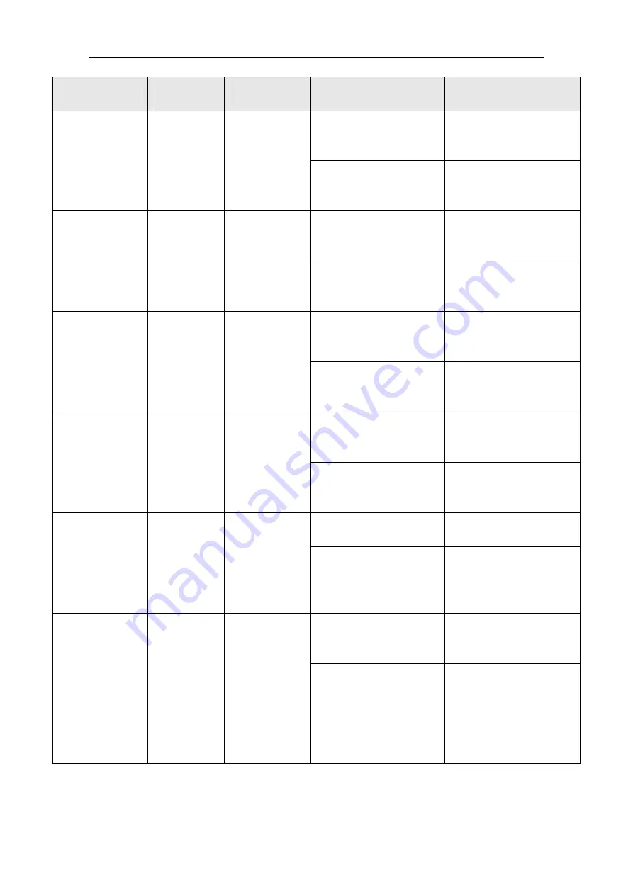
background image


- 27 - 

Malfunction cause 

Malfunction 

code 

Safeguard 

Enter condition 

Resume condition 

Circuit board temperature 

probe is not inserted well 

or loose 

Re-insert temperature 

probe 

Damaged outlet 

water temperature 

sensor 

E1

11 

the unit stopped 

Temperature probe is 

damaged 

Replacement of the 

corresponding temperature 

probe 

Circuit board temperature 

probe is not inserted well 

or loose 

Re-insert temperature 

probe 

Damaged 

backwater 

temperature 

sensor 

E1

12 

the unit stopped 

Temperature probe is 

damaged 

Replacement of the 

corresponding temperature 

probe 

Circuit board temperature 

probe is not inserted well 

or loose 

Re-insert temperature 

probe 

Damaged    air 

temperature 

sensor 

E1

13 

the unit stopped 

Temperature probe is 

damaged 

Replacement of the 

corresponding temperature 

probe 

Circuit board temperature 

probe is not inserted well 

or loose 

Re-insert temperature 

probe 

Damaged Y# coil 

temperature 

sensor 

E1

27 

Y# compressor 

stopped 

Temperature probe is 

damaged 

Replacement of the 

corresponding temperature 

probe 

Power supply phase 

missing 

Check power supply 

Phase sequence 

protection 

E1

01 

the unit stopped 

External power supply 

phase sequence error 

External power supply to 

replace any of the 

three-phase two-phase 

power supply wiring 

Water flow switch is not 

properly access electronic 

control box 

Check and join 

water flow switch 

off 

E1

02 

the unit stopped 

Regulation of water flow 

switch spring preload 

adjustment is incorrect, 

resulting in insufficient 

water flow, but flow switch 

does not close 

To re-install the flow 

switch 

Summary of Contents for CAR-XB

Page 1: ...www econo nl Manual heatpump model Econo CAR XB ...

Page 2: ... 3 1 1 Features 3 1 2 The figure of working principle 4 2 Installation Instruction 5 2 1 Installation 5 2 2 Electrical diagram 10 2 3 System test 11 3 Panel operation 13 4 Function description 21 5 Malfunction protection and code 26 ...

Page 3: ... full consideration of insuring installation as easy as possible Refrigerant circle is a sealed complete system finished by manufacturer No needs for users to connect copper pipes or refrigerant charging Hydraulic circle of system can be connected to hydraulic terminals by two tubes Operating protection System is designed with over voltage under voltage over load protection to insure safe operatio...

Page 4: ... working principle Heat i ng f l ow I nl et heat i ng w at er O ut l et heat i ng w at er 1 Compressor 2 Four way valve 3 Tube in tube heat exchanger 4 Pressure switch 5 Pump 6 Drier and Filter 7 Liquid tank 8 Thermal Expansion Valves 9 Fan 10 Fin tube heat exchanger 11 Gas liquid segregator 12 Low pressure switch 13 High pressure switch ...

Page 5: ...ssible to avoid big pressure drop The machine may be installed above the ground or the roof keeping enough space between the bottom plate and ground In order to assure draining water effectively And the bracket must has enough carrying capacity Hydraulic circle charged with clean water no dust or oil Soft water is recommended Make sure no barrier around the unit ensure the good ventilation of cond...

Page 6: ...ing the machine horizontal disassemble the ground bolt in the pallet after the machine is well located and take the pallet aside Fixation Rubber gasket is recommended to reduce vibration and noise while rivet the bottom plate Water pipe connection Heated water pipe must be packed with thermal isolation material to avoid thermal capacity loss or dew dropping Inlet connection pipe must be equipped w...

Page 7: ...ld be less than 1 000 meters Working water temperature available from 8 50 maximum water pressure 10 bar Wires must be connected according to the instruction of electrical connection diagram Also an all pole air break switch is needed and the pole clearance should be more than 3mm The ground wire must be well connected Ground wire can t be connected to coal gas pipe water pipe or telephone wire Th...

Page 8: ...household waste for disposal there are several possibilities a The municipality has established collection systems where electronic waste can be disposed of at least free of charge to the user b When buying a new product the retailer will take back the old product at least free of charge c The manufacturer will take back the old appliance for disposal at least free of charge to the user d As old p...

Page 9: ...se do exhaust the air in water system before running the machine if you completely finished the circulating water system piping B The water flow switch must be installed at the straight pipeline section of the same level from the elbow valves and other pieces of partial resistance to more than 5 times the diameter C The pipe must be insulated closely in order to improve cooling heating effect and ...

Page 10: ... C O M PR ESSO R Oper at i on panel KM 3 C om p 1 Indoor pum p 0 5 4 3 2 1 0 31 R L S T KM 2 XT 0 TRAN1 TRON2 15μ F 32 33 39 35 unit wiring Model Power Voltage V Power wire mm2 Allowed max current A CAR 20XB 380V 3N 50HZ 342 418 3 0 12 0A attentions of wire connecting All wires must be well connected All wire should avoid touching refrigerant tube If it is not avoidable vibration protection and is...

Page 11: ... tube and drain cock on the water pump 9 Check if there is visual damage caused during transportation 10 make sure all wiring correct Commissioning 1 Make sure all above checking items are passed 2 Open controller cover then connect the power source wires If the power source is three phases check the phase order immediately Red lamp on controller board will light while phase order is correct Check...

Page 12: ...t measurement of the normal operation of the compressor with or without abnormal noise 2 inspection of each unit whether it is normal for the conversion of cold to observe pressure gauge pressure gauge to see whether it is normal 3 to adjust the room air conditioning fan coil water valve so that each room up to a certain flow of water 4 in accordance with the requirements of your good three speed ...

Page 13: ...3 Panel operation Settim Time Chec Model Temp Set ...

Page 14: ... 3 Settime on off Set b7 is for 0 which shows compages timing In the case of running press Settime button shutdown Settime In the case of shutdown press Settime button start Settime Press Settime button then hour time flashing Press time button adjust hour of regular time Then press Settime button minute time flashing Press Time adjust minute of regular time Then press Settime button Settime sets ...

Page 15: ...ttime off time Press Settime button settime off time sets finished Clock function sets Press Settime button long by 5 seconds to enter the function of hour set then hour time flashing Press Time button adjust hour clock Then press Settime button minute time flashing Press Time button adjust minute clock Then press Settime button clock sets finished 4 Check Circulation timing Set b7 is for 1 press ...

Page 16: ...and exit user level parameter set sets temperature Table 1 Parameter Name Parameter Name Parameter Name Parameter Name Cell serial number Factory Factory Factory Factory set set set sets s s s Max Max Max Max Min Min Min Min Refrigeration setting temp P1 P1 P1 P1 12 30 bb Heating setting temp P2 P2 P2 P2 40 bC 25 Management level parameter set Press Set button long by 10 seconds enter management l...

Page 17: ... Factory Factory sets sets sets sets 01 01 01 01 O0 O0 O0 O0 model of running b1 b1 b1 b1 1 0 1 Heat Pump cooling just The number of compressor b2 b2 b2 b2 02 01 02 Compressor the Way of defrost b3 b3 b3 b3 1 0 1 Stop compressor Running Enter the conditions of defrost b4 b4 b4 b4 0 0 1 detection fin temperature and judge detection difference in temperature and judge model switch choose b5 b5 b5 b5...

Page 18: ... b7 b7 b7 0 0 1 circulation timing circulation running every 24 hours compages timing once efficieccy in 24 hour Freezing water protection b8 b8 b8 b8 1 0 1 Protection No protection phase sequence protect choose b9 b9 b9 b9 1 0 1 Protection No protection Compressor cut in temp bA bA bA bA 03 02 08 A lower limit cooling bb bb bb bb 10 2 20 The setting of a ceiling heating bC bC bC bC 50 30 80 water...

Page 19: ...arameter Name Parameter Name Parameter Name Parameter Name Cell Cell Cell Cell number number number number Factory Factory Factory Factory sets sets sets sets Max Max Max Max Min Min Min Min The protection due to too high coil temp in cooling mode C1 C1 C1 C1 63 80 50 The protection due to too low outlet water temp in cooling mode C2 C2 C2 C2 4 10 2 Outlet water temperature is too high to protect ...

Page 20: ...mp C7 C7 C7 C7 3 8 2 C8 C8 C8 C8 10 50 19 Compressor start protection C9 C9 C9 C9 3 minutes 15 minutes 3 minutes Compressor running time meeted conditionds CA CA CA CA 3 minutes 10 minutes 1 minutes Shielded low pressure detection time Cb Cb Cb Cb 3 minutes 60 minutes 0 minutes time for the duration of protection CC CC CC CC 3 Seconds 10 Seconds 1 Seconds time of flow switch detection time continu...

Page 21: ...nter the condition of the outdoor coil temperature d4 d4 d4 d4 3 0 15 Exit the condition of the outdoor coil temperature d5 d5 d5 d5 15 20 0 4 Function description 1 temp control target temp control target is air conditioner return water temp 2 function choice Function choice be decision from Table 3 set b1 when b1 parameter show is 1 then the machine is heat pump but when b1 parameter show is 0 t...

Page 22: ... defrosting of interval firstly the compressor stop in defrosting then the four way valve changes direction the compressor restart for defrosting The same of exit defrosting 6 Set time start and close function choice Can choice Settime start and Settime close through controller Combination can be useful within 24hours and just one time Circle Settime can useful all the time when b7 parameter set i...

Page 23: ...f bE times in an hour then the controller of the fault is locked or else it may resume 13 set the protected number for high and low pressure the water temp of outlet indoor and outdoor the water temp difference of outlet and inlet when the protected number access to set value bE within 1 hour the fault is locked or restore 14 The protection due to too high coil temp In cooling model When cooling t...

Page 24: ...essor will restart meet C9 minutes delay In more than bE times per hour of fault the controller is locked the compressor is no longer restart regardless of whether outlet water temperature reset and display the fault code 17 difference in temperature protection when Water shortage When the unit run for refrigeration or heating in a moment if difference in outwater temperature and backwater tempera...

Page 25: ...ess of whether the reset switch reset and display the fault code 21 Compressor low pressure protection when the compressor start up after Cb minutes then low pressure Switch begin detect low pressure switch off last CC seconds in an hour less than bE times the compressor protected during the period of defrost does not detect low pressure switch when the pressure is restored compressor will restart...

Page 26: ... impact on the power web Therefore in accordance with the controller sets to control their starting or stop 25 Compressor abrasion in balance Running process in accordance with first opened and the first stop the compressor Orderly start and stop In the cycle In order to achieve a balance of all the compressor run time 5 Malfunction protection and code The controller judges various types of malfun...

Page 27: ...e sensor E1 13 the unit stopped Temperature probe is damaged Replacement of the corresponding temperature probe Circuit board temperature probe is not inserted well or loose Re insert temperature probe Damaged Y coil temperature sensor E1 27 Y compressor stopped Temperature probe is damaged Replacement of the corresponding temperature probe Power supply phase missing Check power supply Phase seque...

Page 28: ... flow Outlet water super cooling in cooling mode E1 04 the unit stopped Outlet water temperature is lower than C2 Resetting Parameters Water flow is too small Check water way valve is fully open or change the water pump to increase flow Outlet water super heating in heating mode E1 05 the unit stopped Outlet water temperature is higher than C3 Resetting Parameters Water flow is too small Check wat...

Page 29: ...ng Unit operation will have a period of time scaling phenomenon cleaning Expansion valve opening is too small Adjust thermal expansion valve opening larger System has a leak Refrigerant leak detection and re filling Y low pressure malfunction E1 4Y the Y compressor stopped Dust accumulation fin heat exchanger Unit run period of time will produce dust phenomenon cleaning Circuit board temperature p...

Reviews: