28
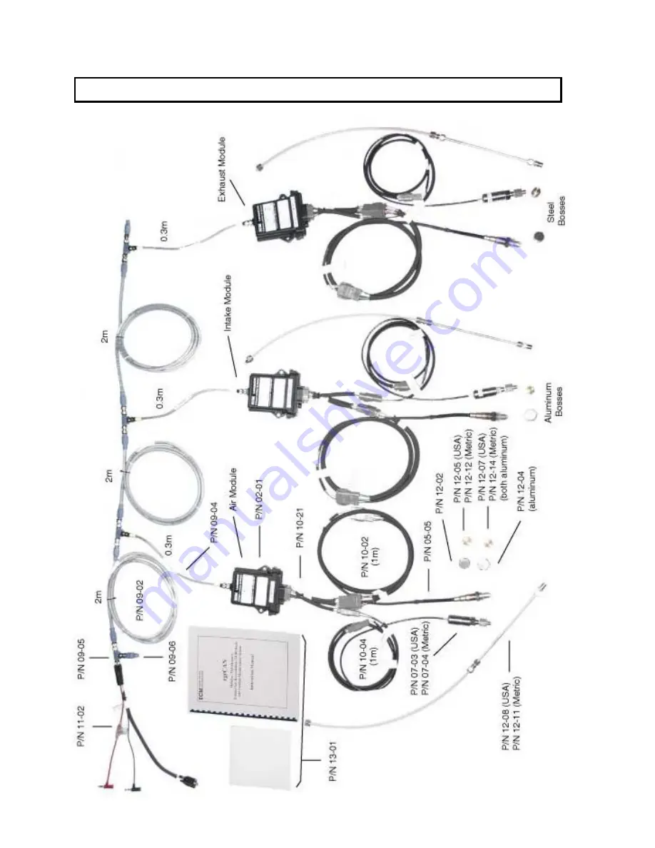
Appendix A: egrCAN Kit Contents (Basic System)
Page 1: ...egrCAN Modular Multichannel Exhaust Gas Recirculation EGR Ratio and Lambda Measurement System Instruction Manual 10 23 2009...
Page 2: ...Rights Reserved No part of this manual may be photocopied or reproduced in any form without prior written consent from ECM ENGINE CONTROL AND MONITORING Information and specifications subject to chang...
Page 3: ...or and the Delta Tables 16 Calibration of the NTK NOx Sensor and the Delta Tables NOxCAN only 18 Calibration of the NGK NOx Sensor and the Delta Tables NOxCANg only 20 Using the dashCAN Display 22 MOd...
Page 4: ...ii Safety Warnings 44 Warranty and Disclaimers 45 A two zone egrCAN system with optional module mounting panel and AC DC Power Supply EGR can be determined at two locations in the engine...
Page 5: ...culate EGRv volume based EGR via the formula EGR 100 O2air O2int O2air O2exh Equation 1 where O2air Parameter O2 O2 output by the air module O2int Parameter O2 O2 output by an intake module An egrCAN...
Page 6: ...2 Figure 1 Basic egrCAN System...
Page 7: ...m of the O2 sensor Mount sensors so that no water will collect on either sensor Mount sensors where air velocity is as low as possible Apply pressure to pressure sensor through a or 6mm teflon hose if...
Page 8: ...Preferentially mount downstream of turbocharger and upstream of exhaust catalyst egrCAN supports the use of multiple exhaust modules As with the intake pressure sensor the exhaust pressure sensor can...
Page 9: ...t the power entry end This is not a requirement but it is the way the power entry devices are manufactured If the distance between the termination resistor see in Figure 1 and the CAN communication de...
Page 10: ...b then the START button Within seconds the modules on the bus will be identified If they are not there is a possibility that two or more modules share the same node id To resolve this hook one module...
Page 11: ...lowing formula calculates the minimum programmable broadcast rate used by all modules given a total number of TPDOs transmitted total for all modules Minimum broadcast rate ms total number of TPDOs fo...
Page 12: ...r Exhaust Modules Fuel Constants Actual or Default of H C 1 85 O C 0 0 N C 0 0 Pressure Sensor Constants Enter sensor specific N and C values written on sensor cable for each module TPDOs Air Module O...
Page 13: ...a N x V C V voltage from sensor See Appendix C Span O2 User enters displayed O2 TPDO data and the actual O2 of the span gas This is how you calibrate the Lambda sensor and the O2 and Lambda measuremen...
Page 14: ...NOpen Error Code ECM CANOpen Error Code PR10 Praw10 bits 10 bit Pressure sensor output voltage unsigned integer format PCF Pressure Correction Factor Lambda sensor pressure compensation correction fac...
Page 15: ...nsigned long format ERCd ECM CANOpen Error Code ECM CANOpen Error Code PR10 Praw10 bits 10 bit Pressure sensor output voltage unsigned integer format PCF Pressure Correction Factor NOx sensor Ip1 pres...
Page 16: ...dbc button is pushed Data package information from all the modules is stored in the one dbc file produced Programs importing the dbc file and applying it to the CAN data transmitted by the modules wi...
Page 17: ...old rev 0x0031 Pulse Red 3x 2s Vsw 9 for 7sec 0x0032 Pulse Red 3x 2s Vsw 30V 0x0041 Pulse Red 4x 2s VS too high 0x0051 Pulse Red 5x 2s RVS too high 0x0052 Pulse Red 5x 2s VHcommanded VHactual 0 5V fo...
Page 18: ...are eight modules each sending two TPDOs the minimum broadcast rate is 5 ms The data transmitted is selected in the Data area of the Configuration Tool Activate the number of TPDOs to be used by click...
Page 19: ...2int Parameter O2 O2 output by an intake module An egrCAN system can have multiple intake modules Thus multiple EGRs can be reported for different locations for EGR distribution studies or stages for...
Page 20: ...nds useful sensor life Calibration of the O2 Lambda Sensor and the Delta Tables The Span O2 task is used to calibrate the O2 sensor This task calibrates both the O2 and Lambda AFR FAR PHI measurements...
Page 21: ...equilibrium readings or readings that match another instrument For this purpose the Delta O2 Table is used The Delta O2 Table found in the task Open Delta Tables allows the user to add a number a del...
Page 22: ...part should be calibrated in a similar manner as it is for the Lambda sensor i e using O2 Span It is important to realize that when in the exhaust of a running engine the NOx sensor is seeing water v...
Page 23: ...mparison to a NOx CLA The NOx level doesn t have to be exactly zero for the zero process For example if it is 12 ppm the Configuration Software will allow this 4 Span NOx the sensor in a running engin...
Page 24: ...ical gas analysis equipment ex NOx Chemiluminescent Analyzer CLA typically have the water removed from the gases before they reach the analyzer Thus classical gas analysis equipment will report dry nu...
Page 25: ...i e same condition as Span O2 IMPORTANT NOTE Do not zero in pure N2 or N2 that has been bubbled through water This will damage the sensor 5 Mount the sensor in a vessel and pass bubbled model gases of...
Page 26: ...3 If the ENT button is pressed the displays will show the units of the parameters 4 PCTG is dIM means dimensionless ex for AFR FAR PHI Lambda In RUN mode four things other than data can be displayed...
Page 27: ...o the lower display The same module can be assigned to both channels or different modules can be assigned to each channel After entering MOd i e press ENT when MOd is displayed the serial numbers of t...
Page 28: ...key 4 Press SYS to return to RUN mode CONF Configure Setup Option CONF setup appears at the end of the setup list on the lower display To enter CONF press the SYS key until MOd appears on the upper d...
Page 29: ...ed This novel convention is sometimes used with lean burn engines 2 AFR and FAR range given for a fuel with an H C ratio of 1 85 3 FAR x 10000 is displayed This is the most commonly used way to expres...
Page 30: ...sor s thread size is identical to that of the exhaust gas oxygen EGO sensors used in current production automobiles with 3 way exhaust catalysts Hex Size 22 mm Tightening Torque 40 4 Nm 30 3 ft lbf fo...
Page 31: ...SS 6MO 6 Metric Fitting on Engine End of Tubing Swagelok SS 400 1 4 tube to NPT USA or Swagelok SS 6MO 1 4RT 6 mm tube to ISO tapered Metric Output Specifications CAN Protocol Broadcast Speed 500 kHz...
Page 32: ...28 Appendix A egrCAN Kit Contents Basic System...
Page 33: ...10 02 1m 3 7 Pressure Extension Cable 10 04 1m 3 8 2m Eurofast 12mm Cable 09 02 3 9 Flexi Eurofast Cable 09 04 0 3m 3 10 Eurofast T 09 05 4 11 Eurofast Terminating Resistor 09 06 2 12 DC Power Cable D...
Page 34: ...rly configured in Stand alone mode or EIB mode depending on how it will be used When LambdaCAN and NOxCAN g modules are sold alone they are delivered in Stand alone mode When LambdaCAN and NOxCAN g mo...
Page 35: ...d tighten ONLY turn from where it is seated If this nut is tightened too much the connector will crack and the enclosure will not be sealed 8 Connect the module to a power supply and a PC via a CAN co...
Page 36: ...Module tab Select the CAN adapter being used Then start the communication Figure A1 Module prepared for Reprogramming P N 11 02 DC Power Cable DB9F Banana Plugs shown or P N 11 01 DC Power Cable To po...
Page 37: ...for Done Message Stop communication and exit program The module is in Stand alone mode To convert a module from Stand alone Mode to EIB Mode 1 Use the Configuration Tool software to Set to EIB Mode 2...
Page 38: ...t Therefore measurements made at the exit of a catalyst will require a Delta O2 Table and a Delta Lambda Table correction to be accurate This is sometimes called H2 Correction Wet versus Dry Measureme...
Page 39: ...his in mind when comparing gas bench measured O2 with Lambda and NOx sensor measured O2 This difference can be corrected for by a Delta O2 Table Lambda Sensor Measured O2 versus NOx Sensor Measured O2...
Page 40: ...CAN or NOxCAN g to an ETAS meter and you want the LambdaCAN or NOxCAN g to match the ETAS meter then you must span the LambdaCAN or NOxCAN g to whatever the ETAS meter says the O2 is in air even if it...
Page 41: ...to open the software 2 Create a new Database In the Database menu select New Give your database a name i e a folder name In INCA a Database means the current working directory Each project is created...
Page 42: ...38 5 Configure the hardware Click on the icon for the workspace you created in step 3 Open the Hardware Configuration icon under the section text 6 Hardware A hardware configuration window will open...
Page 43: ...s example we are using an ETAS ES591 1 Expand the selection tree by clicking the next to the hardware device model Expand the CAN selection and select CAN Monitoring Click OK 7 Associate the dbc When...
Page 44: ...ion Another window will pop up to confirm the device to connect to Click OK 9 Open an Experiment Environment Click on the Experiment Environment button on the upper tool bar to open an Experiment Envi...
Page 45: ...displayed graphs charts gauges numeric etc When complete click OK We have left all configurations at default for this example 12 A new sub window will be added to the Experiment Environment You do not...
Page 46: ...stopped To begin CAN monitoring click on the Start Visualization icon blue triangle on the left hand tool bar To stop CAN monitoring click the Stop Measuring icon black square on the left hand tool b...
Page 47: ...Then press ENT 3 Press until LOCK is displayed Then press ENT 4 50 will be displayed Press until 60 is displayed Then press ENT dashCAN is now LOCKed To unLOCK dashCAN 1 Press SYS until LOCK is displa...
Page 48: ...rCAN s cabling and sensor s on a stopped engine it is best to think out your moves before you make them Route and cable tie all cables away from hot moving sharp or high voltage spark objects Take int...
Page 49: ...fitness for purpose whether express implied or arising by operation of law trade usage or course of dealing are hereby disclaimed The warranty is void if the display head is opened LIMITATION OF REME...
Page 50: ...dashCAN DashCANc SIM300 SIM400 BTU200 To which this declaration relates are in conformity with the essential requirements of the following standards EN61326 1997 A2 2001 Class A Annex A EN61010 1 2001...
Page 51: ......
Page 52: ...Los Altos CA 94023 0040 USA 408 734 3433 Fax 408 734 3432 www ecm co com...