


Configuration
8/05
UDC2500 Universal Digital Limit ControllerProduct
Manual
43
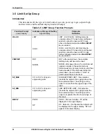
Function Prompt
Lower Display
Selection or Range of Setting
Upper Display
Parameter
Definition
BLOCK
DIS
AL1
AL 2
AL12
ALARM BLOCKING
—Prevents nuisance
alarms when the controller is first powered
up. The alarm is suppressed until the
parameter gets to the non-alarm limit or
band. Alarm blocking affects both alarm
setpoints.
DISABLE
—Disables blocking
AL 1
—Blocks alarm 1 only
AL 2
—Blocks alarm 2 only
AL12
—Blocks both alarms
ATTENTION
When enabled on power up
or initial enabling via configuration, the alarm
will not activate unless the parameter being
monitored has not been in an alarm condition
for a minimum of one control cycle (167 ms).
DIAGAL
DIS
AL 1
AL 2
DIAGNOSTIC
—Monitors the Current Output
and/or Auxiliary Output for an open circuit
condition. If either of these two outputs falls
below about 3.5 mA, then an Alarm is
activated. This configuration is in addition to
whatever was selected for AxSxTYPE.
DISABLE
—Disables Diagnostic Alarm
ALARM 1
—Alarm 1 is diagnostic alarm
ALARM 2
—Alarm 2 is diagnostic alarm
Summary of Contents for UDC2500 Limit
Page 2: ...ii UDC2500 Universal Digital Limit ControllerProduct Manual 8 05...
Page 10: ......
Page 76: ...Input Calibration 66 UDC2500 Universal Digital Limit ControllerProduct Manual 8 05...
Page 126: ......
Page 127: ......
Page 128: ......