


LAN Gateway Firmware V1.2
V1.8 25. April 2012
© 2012 – ECKELMANN AG | BERLINER STRASSE 161 | 65205 WIESBADEN | PHONE +49(0)611 7103-0 | FAX +49(0)611 7103-133 | eckelmann.de
7/34
Connection:
Simultaneous access to up to four clients is possible, of which three via LAN and one via serial connection.
Interfaces:
1x serial as per RS232 standard
1x serial reduced (Rx,Tx) to RS232 standard to CAN2 socket
1x CAN bus interface (RS-232)
1x Ethernet interface (RJ-45 / 10BASE-T)
Voltage supply:
The LAN Gateway is supplied with voltage via the type NT02 power pack (provided). The power pack is coupled
laterally (usually on the left) to the LAN Gateway and it must be supplied with 24 V DC of a separate power
supply (order no. KGLNT23024).
2.2 Use of the LAN gateway as an alarm path
On principle, the LAN gateway can be used as an alarm path. Alarm signalling can only be carried out in active
fetch mode. The precondition for this is a PC with the PC software LDSWin as remote station which can connect
to the LAN gateway via the network. This then calls up the alarms of the LDS system on a cyclical basis. The
LAN gateway is not equipped with an active transmission function for alarms.
The LAN gateway should not be used as the only alarm path. A second alarm path, employing a different
technology e.g. an uplink to the alarm system, telephone dialling device or similar, must be implemented.
When assessing the reliability of a network based alarm path the availability class of all participating
(sub)networks must be considered. As a rule Internet connections do not achieve the availability level of very
good telephone networks.
3 New features compared to the previous version
Version V1.2 of the LAN gateway offers the following new features compared to the previous version:
•
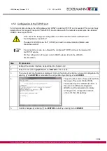
Configuration of the TCP/IP port for communication via LAN. The TCP/IP port for communication via
LAN can now be freely configured, see chapter 4.5.2.
•
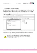
The LAN gateway is now included in the monitoring of the system’s CAN bus nodes and is subject to
failure monitoring by the store computer (alternatively: AL 300), see chapter 4.5.7.
•
A serial connection for the use of LDSWin can also be established, see chapter 5.2.
•
The LAN gateway signals an existing CAN bus communication to the store computer by means of the
continuous illumination of the
LED CAN BUS active
(yellow).
•
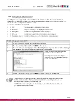
The LAN gateway is equipped with an option for monitoring the processing sequence by means of trace
messages. This function can be configured in detail via the so called trace level, see chapter 4.5.5.
•
The configuration of the LAN gateway can be displayed on the monitor by calling up the function
“showsysconf“
, see chapter 4.5.6.
•
A ping command is available on the monitor for testing the network connection.