background image

INSTALLATION INSTRUCTIONS    


Position the desalination system in a cool and dry location.  Mount the system using all four mounting 
holes. 
 

The  electrical  installation  should  only  be  done  by  a  professional  electrician.    Check  the  correct 
voltage before installing the system.   

 
The cable labeled with the system’s voltage and frequency is to be connected to the power supply.  The 
cable  marked  “FEED  PUMP”  is  to  be  connected  to  the  feed  pump  or  should  be  insulated  /  removed 
where pressurized seawater is available.


SEAWATER FEED PUMP (Optional Equipment) 


Mount the feed pump in a dry location below the waterline of the vessel. Connect the intake of the feed 
pump  with  the  vessel’s  sea  strainer.  Connect  the  outlet  of  the  feed  pump  with  the  intake  of  the 
desalination system located at the pre-filter assembly.  Secure all hoses with the supplied hose clamps.   


PRODUCT WATER TUBING


Connect  the  product  water  outlet  marked  “SAMPLE”  with  a  test  station  of  your  choice.    Connect  the 
product water outlet marked “TANK” to your storage tank. 


REJECT WATER TUBING/HOSE 


Connect  the  outlet  of  the  pressure  control  valve  on  the  back  of  the  flow  control  panel  with  the  1/2” 
reinforced PVC hose to a thru hull fitting preferably above the waterline or drain of your choice. 


FRESH WATER FLUSH KIT 


Install the fresh water flush filter housing at a location near to the desalination system.  Connect the flush 
port of the three-way service valve at the pre-filter assembly of the desalination system with the outlet of 
the flush filter housing marked “OUT”.  Supply pressurized fresh water to the shut off valve of the fresh 
water flush filter housing. 
 

All manuals and user guides at all-guides.com

Summary of Contents for 1200-PRO- 3

Page 1: ...NS 6 7 OPERATION INSTRUCTIONS 8 MEMBRANE CLEANING PROCEDURE 9 MAINTENANCE TIMETABLE 10 PRESSURE VESSEL ENDPLUG CHANGING PROCEDURE 11 ELECTRICAL DIAGRAM 12 TROUBLESHOOTING GUIDE 13 14 HIGH PRESSURE PUM...

Page 2: ...on system By understanding the function importance and normal operation of each part in the system the operator can readily diagnose problems when they first develop Such problems are easily corrected...

Page 3: ...hin film composite spiral wound single pass reverse osmosis element Salt Rejection min 99 5 Salinity Range System 500 900 up to 50 000 ppm TDS NaCl 1200 up to 40 000 ppm TDS NaCl 1500 up to 36 000 ppm...

Page 4: ...cartridge filtration system 2 1 Fresh water flush kit with hose and 316SS hose clamps 3 1 Product water tube 10ft 3m 1 Reject hose 10ft 3m with 2pcs 316SS hose clamps 1 Intake hose 10ft 3m with 2pcs...

Page 5: ...take of the desalination system located at the pre filter assembly Secure all hoses with the supplied hose clamps PRODUCT WATER TUBING Connect the product water outlet marked SAMPLE with a test statio...

Page 6: ...the electrical control panel to the FEED position feed pump only and purge the system until all entrapped air has escaped 6 In the AUTO position press the START button until the pressure on the low p...

Page 7: ...lve and the seacock MEMBRANE STORAGE PROCEDURE If you intend to store your watermaker for more than ten days growth of microorganism will degrade the RO membranes performance The RO membranes should b...

Page 8: ...rning label on side of container and observe all safety precautions on label CAUTION Do not mix different cleaning chemicals together Do not use different cleaning chemicals together at the same time...

Page 9: ...rs or when clogged Pre filters Replace or clean elements and clean housings When system intake pressure drops below 5psi Charcoal flush filter Replace element Every 6 months High pressure pump Change...

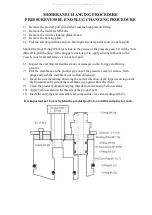
Page 10: ...it in one fast pull 6 Inspect the end plug for hairline cracks or damages on the O rings and O ring grooves 7 Pull the membrane on the product pipe out of the pressure vessel or remove both plugs and...

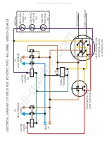
Page 11: ...BUTTON NO SELECTOR SWITCH S2 3 POSITION MAINT 4 CONTACTS NO T1 HIGH PRESS SWITCH S4 NC LOW PRESS SWITCH S5 NO TANK FULL SWITCH S6 NC EXTERNAL MAIN IN ELECTRICAL DIAGRAM CONTROL BOX ECHOTEC PRO BHL SER...

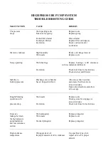
Page 12: ...ilter s Inability to Discharge valve chamber Allow more time to prime build up pressure has air trapped within it and ensure that there are no air suction leaks Open valve chambers and allow air to es...

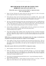
Page 13: ...6D and clean the old Locktite from the plunger bolt 16C and plunger base 16A Replace the plunger with the new one and Locktite the plunger bolt and torque to 120 inch pounds NOTE If there are deposits...

Page 14: ...ere removed from the crankshaft Be certain the bearings are pressed all the way onto the shaft and completely into the crankcase Replace radial shaft seal 11 bearing cover with sight glass 7 and 8 and...

Page 15: ...All manuals and user guides at all guides com...

Page 16: ...The purchaser must pay any transportation or labor expenses incurred in removing and returning the product to the service center The limited warranty does not extend to any system component which has...

Page 17: ...uling rust chemical attack extreme temperatures over 113 F under 33 F drying out or extreme pressures over 1000 psig CAUTION Use of parts not supplied directly by Echo Marine generic parts including b...

Reviews: