Page 13 of 15
8.3.4.2 Sensor 1 Detection Zone Length Setup :
This is used to set up each of the five zones individually. Zone 1 has a range from 1m to 20m and others have a range from
0m to 20m selectable via the pull down menus. The combined total length will not exceed 20m. This will be the same for Zone
2 in a 2 sensor system.
Note: The Trigger Output Length and Buzzer Starting Zone will reset when the Sensor 1 Detection Zones Length is changed. Set the Trigger
Output Length and Buzzer Starting Zone manually as required.
8.3.4.3 Quick Setting:
Not recommended for use
8.3.4.4 Trigger Output Length:
The Trigger Output Length is set at the point where you want the trigger output to start in the detection area. Select the
appropriate Trigger Output Length from the drop down box.
8.3.4.5 Buzzer Starting Zone:
Select the required buzzer starting zone from the drop down box.
8.3.4.6 Sensor 1 Install Angle / Sensor 2 Install Angle:
Horizontal angle cannot be adjusted in the software. Refer to set-up requirements.
8.3.4.7 Distance Display:
If selected, it will display the distance to the object being detected on the monitor. The distance tolerance is +/- 0.03m.
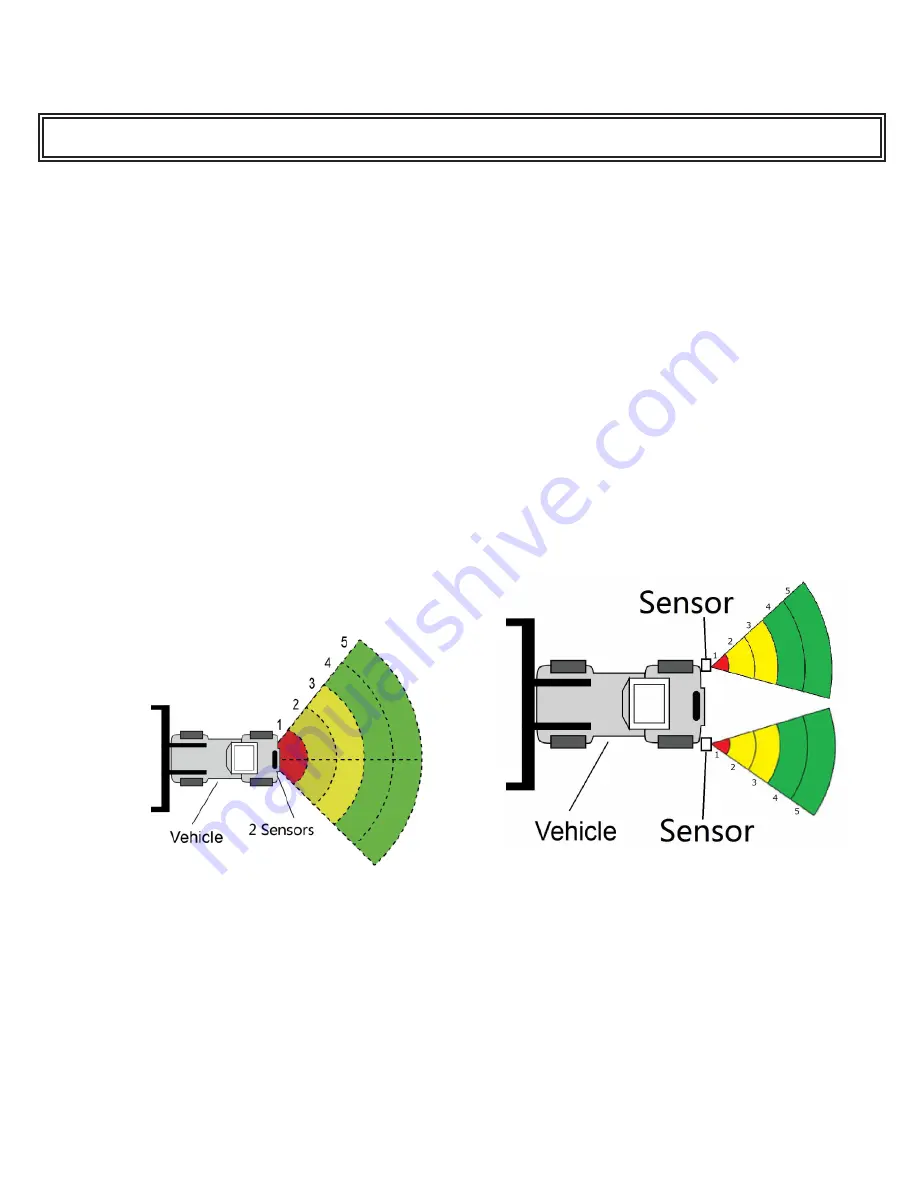
8.3.4.8 Combination Display Setting:
If selected, two sensors will combine to read as one sensor covering a larger area. They must be mounted so they are facing
25° from each other. If this position is not selected, two sensors will detect independently and will show alarm zones for each
sensor.
8.3.5 Download Configuration Data to the Control Box:
Make sure the Configuration Tool is in connected state. Once all the required configurations are selected, all the settings can be
programmed into the Control Box. The “view” interface will also display the status you set.
Click the “Apply” button and it will download the configuration data to the Control Box. Once configuration is downloaded, a
popup window prompts “Config Success” and “Apply Success” will be displayed at the Part D as shown on Figure 22.
Figure 23
Figure 24


