background image

Page 12 of 15

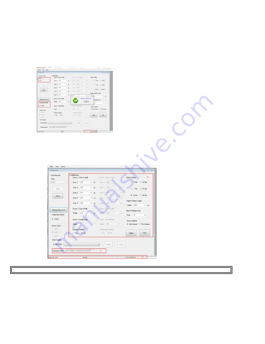
Com Port setup needs to be run every time the Configuration Tool is opened.

NOTE: “Query Success OK” will show once the sensor(s) has been detected.

8.3.3 Reading Configuration from the Control Box:

By clicking the “Open” button via COM, the Configuration Tool will send a query instruction to the Control Box and read 

configuration data from the Control Box. Once the configuration has been read successfully, the latest configuration data is 

displayed in part B, the firmware version information is displayed in part C and connection status is displayed in part D.

WARNING! Connection between the control box and the PC must be maintained while using the configuration tool.

8.3.4 Reading Configuration from the Control Box:

The part B is a configuration group box. This is used to configure “Sensor Zone Length Configuration”, “Quick Setting”, “Sensor 

Zone Width”, “Combination Display”, “Trigger Output Length” and “Buzzer Starting Zone”.

8.3.4.1 Sensor Zone Length :

The detection area length can be set in two ways;

1: Setting each zone individually via the “Sensor 1 Detection Zone Length”. “Sensor 1 Detection Zone Length” can be set

    when you choose sensor number as two sensors.

2: Setting each zone quickly via the “Quick Setting”.

Figure 22

Figure 21

8.3.2.1 Connecting via USB to UART Cable :

Select the COM Mode. To check the COM port number you are using for the connected Control Box on the PC you will need 

to open Windows “Device Manager”.

In the Device Manager window click “Ports (COM & LPT)” and check “Silicon Labs CP210x USB to UART Bridge (COM##)”. 

The “##” represents the number of the port through which the display is currently connected to the PC.

The COM port identified before should be used by selecting it from the drop down list and then click “Open”. When the 

connection is successful, “Com Closed” will change into “Com Opened” at the bottom status bar.

8.3.2 Connecting Control Box:

Summary of Contents for Smartspot EC1011

Page 1: ...d or shorting of electrical connections can cause high current arcing which can cause personal injury and or severe vehicle damage including fire 4 Proper placement and installation are vital to the p...

Page 2: ...ts moving objects including any transportation vehicles motorcycles bicycles pedestrians etc 6 Works effectively in harsh environments and in poor visibility including darkness smoke fog and dust 7 Wi...

Page 3: ...terminal blocks or soldered connections be used with shrink tubing to protect the connections Do not use insulation displacement connectors e g 3M Scotchlock type connectors 2 Route wiring using grom...

Page 4: ...e sold separately Figure 2 6 1 Sensor Installation The radar sensor mounting location is important for proper installation Ideally the sensor should be mounted on the rear center of the vehicle at rou...

Page 5: ...two sensors EC1012 Dual Radar Kit Port D for camera use a plug sealer for IP protection Port E for power and trigger cable through 1 5m power cable and trigger cable Red wire connect to power of the s...

Page 6: ...r two sensor optional Figure 8 Connecting two sensors EC1012 Dual Radar Kit Port D for camera through camera cable that comes with the camera sold separately Port E for power and trigger cable through...

Page 7: ...Page 7 of 15 7 Object Detection Capability 7 1 Detection Pattern 7 1 1 Horizontal Pattern Person Car Truck Person Car Truck Figure 9 Figure 10...

Page 8: ...located towards the edges of the detection area or at an angle Distance An object closer to the sensor is better detected than one which is farther away 7 3 Alerts Description This system provides th...

Page 9: ...uct box The driver should be installed before the USB to serial port connection is made to a PC 1 Double click CP210xVCPInstaller_x64 exe 64 bits system or CP210xVCPInstaller_x86 exe file 32 bits syst...

Page 10: ...e device 8 3 Using the Configuration Tool Software Connect the Control Box Port B to the PC with the USB serial port cable Figure 16 WARNING Ensure that the Control Box is powered and there is NO VOLT...

Page 11: ...n you select COM mode Part B is Control Box configuration which is used to set up the detection zone length width Type 1 sensor cannot be set trigger output length and buzzer starting zone Part C is s...

Page 12: ...uick Setting Sensor Zone Width Combination Display Trigger Output Length and Buzzer Starting Zone 8 3 4 1 Sensor Zone Length The detection area length can be set in two ways 1 Setting each zone indivi...

Page 13: ...Sensor 1 Install Angle Sensor 2 Install Angle Horizontal angle cannot be adjusted in the software Refer to set up requirements 8 3 4 7 Distance Display If selected it will display the distance to the...

Page 14: ...or notes the area where detection occurs 7 Next walk from the center of the rear of the vehicle straight back away from the vehicle When the buzzer quits sounding or overlay disappears the detection l...

Page 15: ...S ABOUT THE PRODUCT DO NOT CONSTITUTE WARRANTIES Remedies and Limitation of Liability ECCO S SOLE LIABILITY AND BUYER S EXCLUSIVE REMEDY IN CONTRACT TORT INCLUDING NEGLIGENCE OR UNDER ANY OTHER THEORY...

Reviews: