Page 1 of 4
P/N 920-5050-00 (Rev E) 2018-06-29
Failure to install or use this product according to manufacturer’s recommendations may result in property
damage, serious injury, and/or death to those you are seeking to protect!
!
WARNING!
1. Proper installation combined with operator training in the use, care, and maintenance of emergency warning devices are
essential to ensure the safety of you and those you are seeking to protect.
2. Exercise caution when working with live electrical connections.
3. This product must be properly grounded. Inadequate grounding and/or shorting of electrical connections can cause high
current arcing, which can cause personal injury and/or severe vehicle damage, including fire.
4. Proper placement and installation are vital to the performance of this warning device. Install this product so that output
performance of the system is maximized and the controls are placed within convenient reach of the operator so that s/he
can operate the system without losing eye contact with the roadway.
5. Do not install this product or route any wires in the deployment area of an air bag. Equipment mounted or located in an air
bag deployment area may reduce the effectiveness of the air bag or become a projectile that could cause serious personal
injury or death. Refer to the vehicle owner’s manual for the air bag deployment area. It is the responsibility of the
user/operator to determine a suitable mounting location ensuring the safety of all passengers inside the vehicle particularly
avoiding areas of potential head impact.
6. It is the responsibility of the vehicle operator to ensure during use that all features of this product work correctly. In use, the
vehicle operator should ensure the projection of the warning signal is not blocked by vehicle components (i.e., open trunks
or compartment doors), people, vehicles or other obstructions.
7. The use of this or any other warning device does not ensure all drivers can or will observe or react to a warning signal.
Never take the right-of-way for granted. It is your responsibility to be sure you can proceed safely before entering an
intersection, driving against traffic, responding at a high rate of speed, or walking on or around traffic lanes.
8. This equipment is intended for use by authorized personnel only. The user is responsible for understanding and obeying
all laws regarding warning signal devices. Therefore, the user should check all applicable city, state, and federal laws and
regulations. The manufacturer assumes no liability for any loss resulting from the use of this warning device.
Do not install and/or operate this safety product unless you have read and understand the safety
information contained
Important!
This unit is a safety device and it must be connected
to its own separate, fused power point to assure its continued
operation should any other electrical accessory fail.
Caution:
When drilling into any vehicle surface, make sure the
area is free from any electrical wires, fuel lines, vehicle
upholstery, etc. that could be damaged
Installation and Operation Instructions
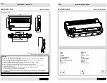
Directional LED (Single colour)
The ECCO ED5050 single colour Directional LED Warning Lamps are bright
and versatile warning lamps which are suited to a wide variety of
applications. Their shallow profile makes them ideal for installation in vehicle
front grilles with minimal modification to the vehicle. This makes them
suitable for fitment to cars, vans, trucks and any vehicle with limited forward
facing flat surfaces, they also lend themselves to covert installations. They
feature wide angle optics and multiple flash patterns, including
synchronisation with other units for simultaneous or alternating operation.
ED5050 single colour models feature 9 LEDs and have 10 flash patterns.
This manual provides information about installation, function, safety,
maintenance and warranty.
CONTENTS:
1 x LED light head
2 x flat brackets
2 x 90 degree brackets
1 x Light Head Gasket/Cushion
4 x Bracket Cushions
2 x countersink screws for flat brackets
2 x pan head pozi screws for 90 deg. brackets
2 x self-tapping screws
1 x installation instructions