background image

32

|

 User Manual

Using the System

32

Password

On:

Enable password

Off:

Disable password

Can be turned to Off so the user can enter and exit menus at will without having to use the password.

If the password option is turned to Off at User Level 1, then only User Level 1 options will be displayed

until a higher level password has been entered. This value is retained on switching off the printer.

Print Height

Allows the user to select a suitable print height for optimum print quality.
This range can be tuned to individual requirements, by adjusting the print height over a range of -30%

to +30%.

Scale Height

This enables a greater print height range and can be used to eliminate deflector plate/gutter clipping

at maximum and minimum drop deflection.

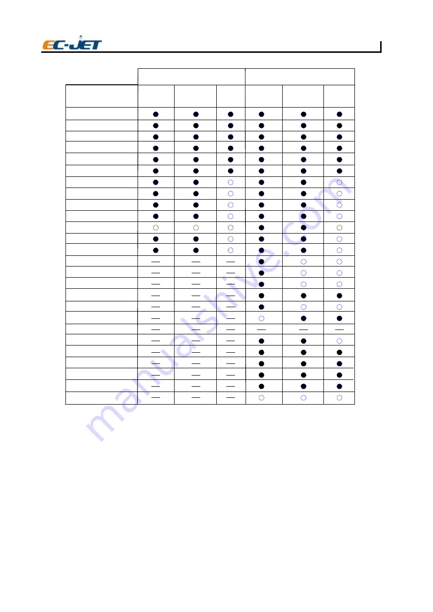
Setup Menu Options

USER LEVEL 1 PASSWORD

USER LEVEL 2 PASSWORD

Jet Off

Jet Running

Printing

Jet Off

Jet Running

Printing

EJ67

Password
Print Height
Scale Height
Print Width
Print Delay
Print Count
Reverse Message
Bold Ratio
Set Time
Set Date
Aux In
Photocell
Shaft Encoder
Conduit Length
Head Height
Print head Code
Ref Modulation
Ink Selection
Calibrate Print Head
Alarm Set Up
Alarm Warning
Change Password
Change Language
Remote Setup Menu
Diagnostic Menu
Solv Add Time

Summary of Contents for EC-JET400

Page 1: ...Excellent EC JET Intelligent Choice USER MANUAL PRINTER Stock Code 835766 EC JET400...

Page 2: ...ed that there may be errors or omissions in this user manual EC JET shall not be liable for any loss or damage arising from the use of any information particulars or errors in this user manual or main...

Page 3: ...TH OR INJURY FROM ELECTRIC SHOCK UNDER NO CIRCUMSTANCES ARE YOU TO ATTEMPT TO OPEN THE PRINTER COVER OR ATTEMPT TO REMOVE OR ADJUST ANY COMPONENTS FITTED WITHIN THE PRINTER ONLY FULLY TRAINED EC JET A...

Page 4: ...all operators should be trained in First Aid and should be aware of the effects of working with flammable and toxic substances All operators should have access to the ink and solvent Material Safety D...

Page 5: ...op 3 Principles of Operation 4 controls and Indicators 5 Front Panel 5 Screen Display 7 LED Status Indicators 7 Start and Stop Keys 7 Cursor Control Keys 8 Function Keys 9 Text Control Keys 9 General...

Page 6: ...0 Password 32 Print Heigh 32 Scale Heigh 32 Print Width 33 Print Delay 33 Print Count 33 Reverse Message 33 Bold Ratio 33 Set Time 33 Set Date 33 Photocell 33 Shaft Encoder 34 Conduit Length 34 Head H...

Page 7: ...int Head Cover Off 50 3 08 Bad Print Head Code 51 3 09 New Print Head Fitted 51 3 10 Charge Calibration Range 51 3 11 Safety Override Detected 51 3 12 Low Pressure 51 3 14 Over Speed Variable Data 51...

Page 8: ...ll Connections 74 Setting up the Shaft Encoder 75 Shaft Encoder Connections 75 Selecting the Encoder Gearing and Print Width 76 Troubleshooting Encoder and Print Width Problems 80 Using the Printer Al...

Page 9: ...ities provided through the menu options By using the SETUP menu certain system information such as the language to be used the date and time etc can be changed Diagnostics All EC JET printers includes...

Page 10: ...f the product and printing can be synchronized using a product detecting sensor The printer consists of a cabinet and a printhead The cabinet houses the electronics module the ink system and a power s...

Page 11: ...he printhead rasters are laid down side by side to form the printed message Leaving Gaps Unprinted drops in a raster carry no charge and are therefore not deflected These drops are captured by a gutte...

Page 12: ...special procedures to clear the nozzle are necessary With EC JET printers the clean up procedures at shutdown are achieved by an automatic flushing system On shutdown the ink is removed from the ink n...

Page 13: ...duced it is possible to charge every drop to a predetermined level The drop stream continues its flight and passes between two deflector plates which are maintained at a constant potential typically p...

Page 14: ...ors User Manual Controls and Indicators This section describes the user interface for the EC JET printer the screen display keyboard keys function keys and cursor control keys Front Panel The front pa...

Page 15: ...Controls and Indicators 6 User Manual 5242 EJ05...

Page 16: ...his indicates that the power is on the printer is ready to print Jet When illuminated the jet is running and the printer is ready to print warning This indicator is illuminated when a warning is issue...

Page 17: ...The left right arrow keys are used to scroll through the multiple choices values of a menu option The cursor keys are also used to move the edit cursor when creating or editing patterns to be printed...

Page 18: ...eft of the character Holding the shift key down while pressing a key will sent to the printer the top left of its character Holding the ctrl key down while pressing a key will sent to the printer the...

Page 19: ...This is useful when the spacing between characters needs to be adjusted to improve readability and or appearance Also this makes it possible to adjust the position along a vertical axis perhaps to ce...

Page 20: ...r Connection The EC JET range of printers are designed to operate on a single phase 50 60 Hz AC supply of 90 to 240 V This means that any AC voltage within this range will power the printer satisfacto...

Page 21: ...earliest possible opportunity Information Messages There are two basic types of information messages these are user prompts and current task information User prompts give helpful information on how t...

Page 22: ...the printhead is clamped in place at the correct distance from the printing surface and start the conveyor Printing should take place immediately and if everything is set up correctly print quality sh...

Page 23: ...he machine may now be switched off by the power switch at the rear of the printer 1 EJ24 CURRENT MESSAGE F1 2 F t n i r P p o t S Check Status F3 4 F g n i t n i r P Change Setup VOD PRESSURE PHASE 00...

Page 24: ...UMBER DATE LOGO REMOTE PRINT STATUS ERROR LIST SETUP PASSWORD PRINT HEIGHT SCALE HEIGHT PRINT WIDTH PRINT DELAY PRINT COUNT REVERSE MESSAGE BOLD RATIO SET TIME SET DATE AUX IN PHOTOCELL SHAFT ENCODER...

Page 25: ...the required option the option is selected by pressing the enter key If the option is a direct command e g Print Height from the SETUP menu the command will be executed Normally however menu options...

Page 26: ...as Key Name QuWei Unique Code PinYing Phonet when pressing F1 to chose Chinese Character Creating a New Message The sequence in which a new message is created depends on the number of messages curren...

Page 27: ...eld This means that its size will remain fixed even as it moves through fields of different character heights As soon as a field is selected by pressing the enter key the cursor will readjust to the c...

Page 28: ...signed a time from which it is to be printed It will continue to be printed until another timed message becomes due This will then print until another timed message becomes due and so on Sequential Nu...

Page 29: ...access to all user menus and functions is allowed Allowed to change User Level 1 and User Level 2 passwords Creating Editing and Deleting Message Fields An example message comprising all types of fiel...

Page 30: ...ential Number Fields Deleting Fields All fields whether Date Time Timed Message Sequential Number Logo or Remote are deleted in the same way Quite simply move the cursor to any character within the fi...

Page 31: ...ough 7 Mon to Sun 1 3 h g u o r h t 1 h t n o m f o y a D d d 6 6 3 h g u o r h t 1 e t a d n a i l u J j j j 2 5 h g u o r h t 1 r e b m u n k e e W w w 2 1 h g u o r h t 1 r e b m u N h t n o M m m...

Page 32: ...stage because we are still editing When editing is finished the dd mmm yy will be replaced with the relevant information from the current date NOTE If you do move the menu cursor in the DATE menu pres...

Page 33: ...t to 5 with a Start Number of 00 the counting sequence would be 0 5 10 15 and so on Range 1 through 127 No of Repeats Number of times the sequential number will be printed before it is incremented by...

Page 34: ...the Time option and press the enter key to display the TIME menu Choose from the range of formats hh mm 24 hour clock hours and minutes hh mmpm 12 hour clock hours and minutes hhmm 24 hour clock hour...

Page 35: ...he second would print from 12 noon to 15 00 and the third would print from 15 00 to 10 15 and so on To create the timed message use the menu cursor to locate and change the options as shown in the TIM...

Page 36: ...isplay the SELECT FIELD TYPE menu Locate the Timed Message option and press the enter key to display the TIMED MESSAGE menu Create the timed message using the menu cursor to locate and change the opti...

Page 37: ...s to be downloaded into the field from the remote computer Press the enter key and the EDIT MESSAGE screen will be displayed Note that the remote field we have created is denoted by a row of asterisks...

Page 38: ...ys ERROR LIST menu see below Count Shows the number of prints made by the printer This value can be reset to 0 zero from the SETUP menu see later Changing the System Setup Status Shows the operational...

Page 39: ...rrors reported on the status line of the display The ERROR LIST menu can be viewed by pressing F2 from the CURRENT MESSAGE screen to display the PRINT STATUS screen then press F1 to display the ERROR...

Page 40: ...00 000 Jet Off 2006 03 24 14 01 38 Print Delay Print Count Reverse Message Bold Ratio Set Time Set Date Aux In Photocell Shaft Encoder Conduit Length Head Height Print Head Code Ref Modulation Ink Sel...

Page 41: ...ndividual requirements by adjusting the print height over a range of 30 to 30 Scale Height This enables a greater print height range and can be used to eliminate deflector plate gutter clipping at max...

Page 42: ...his option Off the message will be printed as on the display On the message will be printed right to left Bold Ratio A bold ratio of 1 is equivalent to standard print e g one vertical line of drops pe...

Page 43: ...place a in front of the value The value may be entered simply as X Xm NOTE Care must be exercised with this option poor printer performance will result if incorrectly set This will automatically chan...

Page 44: ...or for any reason that it cannot print e g when the printhead cover has been removed As soon as the printer is ready to print or is printing the alarm will switch off Ink and Solvent The external ala...

Page 45: ...y a short cut may be used by pressing the D key on the keyboard The menu option selected will be the one which was selected the last time the DIAGNOSTICS menu was used The options available from the D...

Page 46: ...t selectable and has a parameter entry is used to display information only and the user cannot change the value e g Set Pressure in user diagnostics Start Print Makes the printer ready to print i e as...

Page 47: ...ease Wait Quick Start Jet Starts the jet without printing Please note this operation does not check any of the following Ink Solvent Service time Phase VOD Modulation i e it simply switches the jet on...

Page 48: ...hutdown will be performed for all other inks if the time since the previous flush shutdown is less than 15 minutes 30 minutes for a 4 metre conduit a non flush shutdown will be performed NOTE For a su...

Page 49: ...he jet has been running the filter life expired and the time due until service The menu is called up from the DIAGNOSTICS menu Power On Number of hours power has been on Jet Running Number of hours th...

Page 50: ...nt pressure set on the pressure DAC Your local distributor may ask you to use this option to 1 Diagnose and or check for any pressure loss 2 Purge the filter without resetting the filter time e g if c...

Page 51: ...ent It is not recommended that solvent is used frequently to remove ink from the front panel and LCD screen as this can lead to deterioration of the membrane surface Front Panel and LCD Wipe the front...

Page 52: ...ll run down the printhead and can be collected in the container for disposal Allow the printhead to dry completely by letting it stand for a few minutes Do not dry the printhead with a cloth or towel...

Page 53: ...he solvent bottle carefully ensuring that it is empty and refit the filler cap Now fill the machine with ink in the same way The ink cannot be seen as it leaves the bottle and drains into the system i...

Page 54: ...ned filter in its housing or fit a replacement filter if it is changed 5 Close up the cover To the machine that its number after SN C5000 1 Hold up the front of machin lightly 2 and the air filter sho...

Page 55: ...hen the software detects a problem which affects printing 2 00 Print Head Temperature 2 01 Deflector Voltage 2 02 Charge 2 03 VOD 2 04 300V Power Supply 2 05 Temperature Deflector 2 06 Ink Tank Empty...

Page 56: ...off all valves closed 300V off these settings cannot be altered until the print failure has been cleared i e the jet cannot be restarted The following pages give a brief description of each Print Fai...

Page 57: ...incorrectly Check the Printhead and Modulation values printed on the printhead serial number label found on the conduit with the stored values see Changing the System Setup Build up of ink on the sen...

Page 58: ...ny 3 00 No VOD Adjustments This warning can occur when the jet is being started or when the jet has been running for some time Possible causes Printhead code values are set incorrectly Check the Print...

Page 59: ...d DO NOT put in more than one bottle If the ink low condition is detected before the jet is started then the jet cannot be started until the ink tank is replenished If the condition is detected while...

Page 60: ...printhead code in the SETUP menu If the wrong type of printhead has been detected for any reason the modulation frequency voltage etc will all be incorrect Therefore the jet will not break up properl...

Page 61: ...istributor 3 17 Memory Corrupt The system will still function but some values may have been reset to their defaults Possible cause The battery backup has failed exhausted battery Recharge the battery...

Page 62: ...fault diagnosis sequence is as follows 1 Collect as much information as possible on ALL the symptoms that the printer is displaying including error messages print samples and signs of electrical or m...

Page 63: ...ult to identify the cause of the problem but some faults have similar symptoms making accurate diagnosis a little more difficult For example a low modulation problem can give similar symptoms to high...

Page 64: ...ults shaft encoder slipping FC09 Squashed print Pattern not blurred Deflector Voltage Faults FC10 Product tilting along the axis of the conveyor travel Vibration Problems FC36 Product tilting across t...

Page 65: ...the message on its own is not enough to identify the problem refer to the following list of symptoms to identify the possible cause of the fault The list is organised to group the symptoms into the fi...

Page 66: ...Problems nozzle blockage FC32 Messy printhead at start up Jet Alignment Problems nozzle out of alignment FC32 No VOD adjustment on start up Pressure Loss mechanical FC12 Blocked gutter GutterProblems...

Page 67: ...jet is misaligned on the gutter the least deflected drops may catch the edge of the gutter This will cause the loss of the drops from the top of the print pattern As printing continues the ink will b...

Page 68: ...se spray of drops Cause and Cure Check the EHT settings and connections Check the printhead cover slot for an obstruction which may be a build up of ink If the printhead cover is badly out of place on...

Page 69: ...r tightening of the connectors onto the threaded stud of the filter body can cause a partial pressure loss by constricting the olive and reducing the size of the flow aperture the actual filter membra...

Page 70: ...a very small orifice and it is possible for this orifice to become blocked in a number of ways for instance dried ink foreign debris introduced into the ink supply or contamination of ink types The m...

Page 71: ...ertical position 4 Activate the Clear Nozzle routine by pressing the enter key 5 The status line will indicate that the printer is clearing the nozzle 6 Apply small amounts of solvent to the inverted...

Page 72: ...rint quality is the most common indicator of vibration problems This is because the print drops are relatively stable while in flight so vibration in either the product being marked or the printhead i...

Page 73: ...stration below shows the displacement of rasters in response to high frequency vibration Notice how characters are distorted in width as the product tilts under the printhead Product tilting from side...

Page 74: ...on is likely to be coming from the printhead To test for printhead vibration pass a piece of paper under the printhead in the same way as described above but this time hold the printhead with your oth...

Page 75: ...e printhead more often than would be expected To understand what is happening consider that the stream of drops is relatively stable once in flight Therefore if the printhead suffers vibration or sudd...

Page 76: ...ace What actually happens is that when the system detects a product passing the photocell it will delay printing by counting the number of rasters it would have printed until that count becomes equal...

Page 77: ...s in position for printing In response to this if a Delay Has been set the printer software Will begin to count rasters It will not print until the number Of rasters counted is equal to the Delay valu...

Page 78: ...ng that the printer is unable to finish printing it Before the next product arrives This causes the Overspeed warning message to be displayed Message Would end here Message started here Photocell dete...

Page 79: ...Requirements Voltage 90 V 3 A to 240 V 1 5 A a c 50 60 Hz Power rating 200 VA This equipment is a Class 1 earthed Electrical connections at the rear of the cabinet comply with the extra low voltage s...

Page 80: ...cro 100 micron Construction Printhead Machined Acetal body Cover tube Stainless steel grade 304 Conduit adaptor Stainless steel grade 303 Dimensions Conduit length 2 m Throw Distance recommended Micro...

Page 81: ...e and with a clean power supply i e free from electrical interference The printer physical dimensions in millimetres are as follows 550 wide x 230 high x 450 deep The printer weighs 23 kg not includin...

Page 82: ...D BY A QUALIFIED ELECTRICIAN EC JET CAN ACCEPT NO RESPONSIBILITY FOR ANY DAMAGE CAUSED TO EITHER MACHINE OR PERSONNEL DUE TO INCORRECT OR FAULTY WIRING Attaching the Printhead to the Production Line T...

Page 83: ...roduct before the product reaches the printhead as close to the printhead as possible and at a distance from the product which gives consistently reliable triggering when a product passes it A delay b...

Page 84: ...some variation using the Print Width parameter but the initial selection of the encoder and gearing is critical EC JET offer a range of shaft encoders 2500 pulses per revolution 5000 pulses per revolu...

Page 85: ...is adequate Step 4 Calculate the print width from the pitch factor and enter it Step 5 Check print samples for performance Step 1 Define the Required Raster Pitch for the Application For each raster t...

Page 86: ...ance the product will travel for each cycle of the encoder output signal The encoder pitch will be multiplied by the pitch factor a whole number to give the actual raster pitch This should be as close...

Page 87: ...nges in the required pitch However the cost of the encoder will be higher and there may be limitations in terms of speed this is covered in later sections Step 3 Check the Expected Print Performance A...

Page 88: ...slightly higher than the quoted maximum line speed for the raster achieved at the expense of a small gap between the printed drops The encoder gearing chosen has an encoder pitch of 0 040 mm Step 2 an...

Page 89: ...enu set Shaft Encoder to Off Note down the original Print Width setting then set Print Width to 0 b Note the original Print Delay setting Multiply this by the original Print Width setting Enter the ne...

Page 90: ...s After a main ink filter change the filter must be completely filled with ink before the system is run For this purpose a Filter Purge option is available from the DIAGNOSTICS menu This procedure sho...

Page 91: ...thing other than ideal pitch Ideal Pitch Otherwise known as single pitch this is dependent on the raster i e printer type being used Printers with the faster rasters have an increased pitch capacity b...

Page 92: ...e Five products 1 metre per second line speed 5 5 5 products 1 second 5 products 1 second x 0 2 metre per second line speed EJ123 5 products 1 metre LINE SPEED PER PRODUCT FREQUENCY m s Product Pitch...

Page 93: ...dia Pvt Ltd Address 5095 East Airport Drive City of Ontario CA 91761 USA Tel 1 909 390 1888 Fax 1 909 390 5388 Address Via Molino Rosso 10F 40026 Imola BO Italy Tel 39 0542 1890315 Fax 39 0542 1890314...

Reviews: