EBARA 100 DL3FU 61.5 Operating Instructions, Installation & Maintenance Manual Download Page 5

5

EBARA 

PUMPS AMERICAS CORPORATION

www.pumpsebara.com

(t) 803.327.5005 (f) 803.327.5097

rev. 01/21

EBARA Submersible Sewage Pumps
Operating, Installation, and Maintenance


DL3FU / DL3MFU / DL3KFU / DL3KMFU / DDL3FU / DV3FU/ DML3FU 


INSTRUCTION MANUAL                                      

        P.4


PM32U


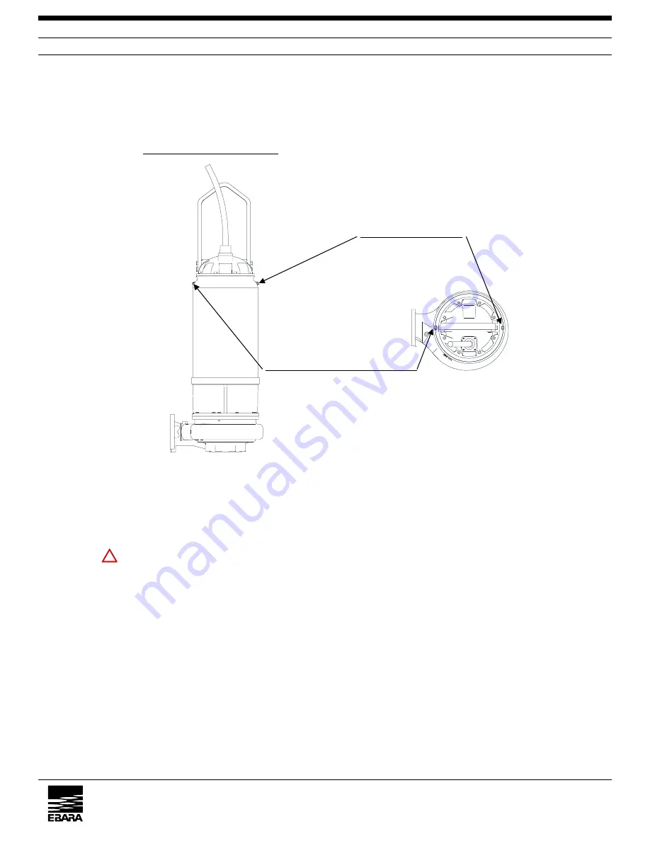
3.1.1  Internal Liquid Supply (Figs. 1, 2 and 3) 


2~5HP(1.5-3.7kW) models come standard without internal cooling system and are shipped with proper 


oil capacity per Table 2.    7.5~60HP(5.5~45kW) are standard with internally cooled system (no oil fill 


required) and are shipped with proper coolant capacity per Table 1. 


Fig. 1                                 Fig. 2 


The motor shaft is sealed with a mechanical seal. The coolant chamber provided between the 


two sealing stages can be filled with coolant by standing the pump vertical


on a level surface 


and remove plugs 

Coolant supply hole

 and 

Air vent & full level check hole


    CAUTION: 

THE SEAL CHAMBER MAY BE UNDER PRESSURE. HOLD A RAG OVER 


THE PLUG TO PREVENT SPLATTER. 


Pour the specified coolant into the coolant chamber through 

Coolant supply hole

 until the 


coolant flows out of 

Air vent & full level check hole

. (See Table 1) 


After the coolant chamber is filled to the specified level, plug the two holes.   


!

Air vent & full level check hole 

50%: Propylene Glycol


50%: Water 

Coolant supply hole 

COOLANT (Internal liquid) 

Summary of Contents for 100 DL3FU 61.5

Page 1: ...Submersible Wastewater Sewage Pump Model DL3FU Operating Instructions Installation Maintenance Manual EBARA Pumps Americas Corporation ...

Page 2: ...E WASTE WATER PUMP JOB No EBARA SER No ITEM No EQUIP 60Hz Ver SET MODEL DL3FU DL3MFU DL3KFU DL3KMFU DDL3FU DV3FU DML3FU 5 K HIRAMOTO Jan 28 2019 4 APPROVED BY 3 M IMAFUKU Jan 25 2019 REVISED P3 5 7 8 10 12 ISSUED BY Submersible MP Dev Eng Sect 2 EBARA PUMPS AMERICAS CORPORATION www pumpsebara com t 803 327 5005 f 803 327 5097 rev 01 21 ...

Page 3: ...nstallation P 9 4 Electric Wiring P 13 4 1 Power Cable Connection P 13 4 2 Grounding P 16 4 3 Protective Device Leads Connection P 17 5 Operation P 18 5 1 Operational Limitations P 18 5 2 Checking Rotation Direction P 18 5 3 Cautions for Operation P 20 5 4 Operation P 20 5 5 Cautions during Operation P 20 6 Maintenance and Overhaul P 21 6 1 Daily Checks P 21 6 2 Monthly Checks P 21 6 3 Annual Chec...

Page 4: ...is immediately clear DANGER indicates a potentially hazardous situation which if not avoided will result in death or serious injury WARNING indicates a potentially hazardous situation which if not avoided could result in death or serious injury CAUTION indicates a potentially hazardous situation which if not avoided may result in minor or moderate injury or possible damage to the equipment or mach...

Page 5: ...lant capacity per Table 1 Fig 1 Fig 2 The motor shaft is sealed with a mechanical seal The coolant chamber provided between the two sealing stages can be filled with coolant by standing the pump vertical on a level surface and remove plugs Coolant supply hole and Air vent full level check hole CAUTION THE SEAL CHAMBER MAY BE UNDER PRESSURE HOLD A RAG OVER THE PLUG TO PREVENT SPLATTER Pour the spec...

Page 6: ...100 DL3FU 637 38 8 80 DL3MU 61 5 OPT 9 5 100 DL3FU 645 42 80 DL3FU 62 2 OPT 11 6 150 DL3FU 67 5 23 80 DL3MFU 62 2 OPT 11 1 150 DL3FU 611 19 1 80 DL3FU 63 7 OPT 11 6 150 DL3FU 615 22 5 80 DL3MFU 63 7 OPT 11 6 150 DL3FU 618 30 7 80 DL3FU 65 5 23 5 150 DL3FU 622 33 2 80 DL3MFU 65 5 23 5 150 DL3FU 630 38 7 80 DL3FU 67 5 23 150 DL3FU 637 35 8 80 DL3CMFU 67 5 23 8 150 DL3FU 645 39 80 DL3FU 611 19 3 200 ...

Page 7: ...minus terminal of the DC 500V Megger to the G terminal of the cable or a motor bolt Touch the plus terminal of the Megger to L1 phase or L2 phase or L3 phase of the cable and read the insulation resistance Also touch the plus terminal of the Megger to P1 or P2 and P3 or P4 with the minus terminal G connected as above and read the insulation resistance CAUTION DO NOT CONNECT THE TWO MEGGER TERMINAL...

Page 8: ... when water is restored to a safe level 2 Pump location relative to pump pit water inlet If the pump is installed near the pump pit water inlet the incoming flow to the pump can be considerably turbulent the influent liquid can shake the pump and cause the cable s to be whipped vigorously resulting in damage Therefore the pump should be located as far from the water inlet as possible or an influen...

Page 9: ...ansported or installed Attach a rated lifting chain or strap to the pump lifting bail and install the pump 3 This pump must not be installed on its side Ensure that it is installed upright on a secure base 4 Install the pump at a location in the tank where there is the least turbulence 5 If there is a flow of liquid inside the tank support the cable where appropriate See Fig 6 6 Install piping so ...

Page 10: ...After the pump is thoroughly checked verifying it is in order lift the pump body and fit the sliding guide of the pump body to the guide pipe WARNING USE CAUTION DURING PUMP INSTALLATION AND REMOVAL TO MINIMIZE CONTACT BETWEEN PUMP AND ANY MATERIAL THAT CAN GENERATE AN IGNITION SOURCE SUCH AS A SPARK HAVE FIRE SUPPRESSION EQUIPMENT ON HAND Fig 7 Guide pipe 304 Stainless Steel contacts arm attachme...

Page 11: ...p body slowly along the pump guide WARNING CAUTION SHOULD BE TAKEN DURING PUMP INSTALLATION AND REMOVAL TO MINIMIZE CONTACT BETWEEN PUMP AND ANY MATERIAL THAT CAN GENERATE ANY IGNITION SOURCE SUCH AS A SPARK HAVE FIRE SUPPRESSION EQUIPMENT ON HAND 3 The pump is automatically connected to the discharge elbow Sliding guide attaches to support bar 420 Stainless Steel Pump rotates around point of supp...

Page 12: ...he pump cannot slide down smoothly the guide pipe may not be vertical or the lifting method may be wrong Check these points to determine the cause for correction After the pump is installed attach the chain to the hook of the floor frame When the pump is installed indoors it is a good idea for convenience sake that a hoist for example be provide on the ceiling or surface platform so that it can be...

Page 13: ...ed for the appropriate start system as shown in Fig 10 b Loose connections will stop the pump Make sure all electrical connections are secure to prevent short circuit The electric wiring for a submersible motor is no different from an ordinary motor except the direction of rotation cannot be easily verified Wiring to wrong terminals results in reverse rotation To prevent this and to achieve best r...

Page 14: ...3FU INSTRUCTION MANUAL P 13 PM32U Output 2 to 10HP 208 230V 460V P1 P2 T2 T1 T3 L1 L2 L3 R S T G P3 P4 THERMAL PROTECTOR LEAKAGE DETECTOR T8 T7 T9 T4 T5 T6 T1 T2 T5 T6 T3 T4 P1 P2 T8 T7 T9 L1 L2 L3 R S T G P3 P4 THERMAL PROTECTOR LEAKAGE DETECTOR G GRN L1 RED T1 T7 L2 WHT T2 T8 L3 BLK T3 T9 T4 T5 T6 P1 RED P2 WHT P3 BLK P4 ORG G GRN L1 RED T1 L2 WHT T2 L3 BLK T3 T4 T7 T5 T8 T6 T9 P1 RED P2 WHT P3 ...

Page 15: ...3FU INSTRUCTION MANUAL P 14 PM32U Output 15 to 30HP 208 230V 460V T9 T1 T3 T6 T7 T2 T5 T8 G P1 P2 P3 P4 THERMAL PROTECTOR LEAKAGE DETECTOR R T S L1 L2 L3 T4 T9 T1 T3 T6 T4 T7 T2 T5 T8 G P1 P2 P3 P4 THERMAL PROTECTOR LEAKAGE DETECTOR R T S L1 L2 L3 G GRN L1 RED T1 T7 T6 L2 WHT T2 T8 T4 L3 BLK T3 T9 T5 P1 RED P2 WHT P3 BLK P4 ORG G GRN L1 RED T1 L2 WHT T2 L3 BLK T3 T4 T7 T5 T8 T6 T9 P1 RED P2 WHT P3...

Page 16: ...is the proper one labeled G Also verify that grounding continuity has been established inside the motor by checking that ground wire labeled G is electrically conductive with the bolt on the top of the motor to be stripped of paint to bare metal surface Ground the motor according to local codes Ground terminal Ground wire Ground plate G L Table 3 Example Motor classification Grounding resistance M...

Page 17: ...rminals P3 and P4 for the leakage detector to P3 and P4 of the same control connector Table 4 shows detailed specifications regarding protective devices Table 4 Thermal detector Leakage detector Type 9700K 66 215 OLV 5 float type Acting Temperature Reset Temperature 140 5o C 85 10o C N A Contact rating AC 115V 230V 18A 12A max AC 300V 0 5A max Contact type normally closed b contact normally closed...

Page 18: ...te values of the rated values provided the frequency variation does not exceed 5 of rated frequency 5 2 Checking Rotation Direction Figs 12 and 13 Check the motor for rotation direction by the following procedure after the pump has been installed in the pump pit A reversing pump is no problem if operation is not prolonged 1 If the pump performance curve is available Open the sluice valve on the di...

Page 19: ...Normal Pump Performance 2 If the pressure gauge or compound pressure gauge is not installed on the discharge pipe if checks of the rotating direction of the pump in the water as described above cannot be performed proceed as follows Lay the pump on the ground Turn switch on and off instantaneously and check visually the rotation direction through the discharge bore of the pump The rotating directi...

Page 20: ...d Start motor Note A pump of lower shut off power than rated horsepower may be started with the valve closed In such case open the valve within 1 minute after motor start CAUTION DO NOT RUN THE MOTOR IF REVERSE FLOW OCCURS 2 Stopping Stop motor Turn off power Note A pump of lower shut off power than rated horsepower may be stopped after the valve is closed 5 5 Cautions During Operation Pay attenti...

Page 21: ...ng items at least once a month 1 Discharge pressure Check pump discharge pressure and discharge flow rate if flow meter is provided 2 Insulation resistance Operation is safe as long as insulation resistance is more than 1MΩ If the insulation resistance is still higher than 1MΩ but there is a sharp decline from a certain value check the cables and or overhaul is required 6 3 Annual Checks Even if t...

Page 22: ...surface conditions for abnormal conditions CAUTION THE SEAL CHAMBER MAY BE UNDER PRESSURE HOLD A RAG OVER THE PLUG TO PREVENT SPLATTER 2 Mechanical seal upper a Lift the pump out of the pump pit and stand it on the floor in a vertical position Unplug Leak check hole in the intermediate casing of the pump b If no liquid leaks from Leak check hole the mechanical seal upper in Fig 14 is in satisfacto...

Page 23: ... Pumps Operating Installation and Maintenance DL3FU DL3MFU DL3KFU DL3KMFU DDL3FU DV3FU DML3FU INSTRUCTION MANUAL P 22 PM32U 2 5HP 1 5 3 7kW 7 5 60HP 5 5 45kW Fig 14 Drain hole plug Leak check hole plug Mechanical seal lower Mechanical seal upper Mechanical seal upper Mechanical seal lower Drain hole plug Leak check hole ...

Page 24: ...mechanical seal has been replaced with a new one reassemble the pump and supply the specified internal liquid as well At this point turn the rotating body by hand to ensure that it turns smoothly Also check for coolant leaks WARNING USE CAUTION WHEN TURNING THE IMPELLER TO AVOID INJURY 4 Rotor a After checking the coolant put your hand through the pump discharge and turn the impeller Use caution w...

Page 25: ... 2 Key AISI 316 Stainless Steel 1 729 1 Spring Washer AISI 304 Stainless Steel 4 071 Side Plate ASTM A48 CL 30 Cast Iron 1 729 2 Spring Washer AISI 304 Stainless Steel 3 080 Bushing Steel Steel 1 729 3 Spring Washer AISI 304 Stainless Steel 1 111 Mechanical Seal 1 set 801 Rotor 1 114 Oil Seal 1 802 Stator 1 115 1 O ring NBR 1 811 Submersible Cable 1 115 2 O ring NBR 1 814 Motor Frame ASTM A48 CL 3...

Page 26: ...213 Air Vent Valve B36 No 272 Brass 1 080 Bushing Steel Steel 1 412 Guide Plate AISI 304 Stainless Steel 4 111 Mechanical Seal 1 set 729 1 Spring Washer AISI 304 Stainless Steel 4 114 Oil seal 1 729 2 Spring Washer AISI 304 Stainless Steel 4 115 1 O ring NBR 1 729 3 Spring Washer AISI 304 Stainless Steel 8 115 2 O ring NBR 1 729 4 Spring Washer AISI 304 Stainless Steel 3 115 3 O ring NBR 1 729 5 S...

Page 27: ...ron 1 412 Guide Plate AISI 304 Stainless Steel 4 111 Mechanical Seal 1 set 665 ICS Housing ASTM A48 CL 30 Cast Iron 1 114 Oil seal 1 729 1 Spring Washer AISI 304 Stainless Steel 4 115 1 O ring NBR 1 729 2 Spring Washer AISI 304 Stainless Steel 1 115 2 O ring NBR 1 729 3 Spring Washer AISI 304 Stainless Steel 4 115 3 O ring NBR 1 729 4 Spring Washer AISI 304 Stainless Steel 4 115 4 O ring NBR 1 729...

Page 28: ...Iron 1 665 ICS Housing ASTM A48 CL 30 Cast Iron 1 111 Mechanical Seal 1 set 729 1 Spring Washer AISI 304 Stainless Steel 4 114 Oil seal 1 729 2 Spring Washer AISI 304 Stainless Steel 1 115 1 O ring NBR 1 729 3 Spring Washer AISI 304 Stainless Steel 4 115 2 O ring NBR 1 729 4 Spring Washer AISI 304 Stainless Steel 4 115 3 O ring NBR 1 729 5 Spring Washer AISI 304 Stainless Steel 4 115 4 O ring NBR ...

Page 29: ...36 No 272 Brass 1 071 Side Plate ASTM A48 CL 30 Cast Iron 1 412 Guide Plate AISI 304 Stainless Steel 4 107 Wearing Ring CAC406 Bronze 1 665 ICS Housing ASTM A48 CL 30 Cast Iron 1 111 Mechanical Seal 1 set 729 1 Spring Washer AISI 304 Stainless Steel 4 114 Oil seal 1 729 2 Spring Washer AISI 304 Stainless Steel 4 115 1 O ring NBR 1 729 3 Spring Washer AISI 304 Stainless Steel 4 115 2 O ring NBR 1 7...

Page 30: ... Cast Iron 1 412 Guide Plate AISI 304 Stainless Steel 4 072 Side Ring ASTM A48 CL 25 Cast Iron 1 665 ICS Housing ASTM A48 CL 30 Cast Iron 1 107 Wearing Ring CAC406 Bronze 1 729 1 Spring Washer AISI 304 Stainless Steel 4 111 Mechanical Seal 1 set 729 2 Spring Washer AISI 304 Stainless Steel 1 114 Oil seal 1 729 3 Spring Washer AISI 304 Stainless Steel 4 115 1 O ring NBR 1 729 4 Spring Washer AISI 3...

Page 31: ...lve operation Insufficient capacity o Air suction o System head too high o Clogged discharge pipe Pressure too high o Clogged pump or strainer Pressure too low o Air accumulation in pipe o Internal pump wear o Wrong direction rotation o Liquid viscosity different from design value o Damaged impeller o Raise water level in pump pit o Recheck requirements o Clean discharge pipe o Clean strainer impe...

Page 32: ...__ RB __________ WB ________ Amperage Check 1________ A __________ B____________ C __________ 2________ A __________ B____________ C __________ FL Amps ____ 3________ A __________ B____________ C __________ Performance Test 1________ GPM ____ TDH ________ 2________ GPM ____ TDH ________ Water Level ________ 3________ GPM ____ TDH ________ Comments __________________________________________________...

Page 33: ...used in sewage applications be sure to clean and disinfect pumps or parts thoroughly with a solution of 25 Bleach and repackage securely so no further damage will occur On the exterior of packaging please note Pump Has Been Disinfected All returns shall have an RMA number clearly written on exterior of packaging with a copy of the RMA paperwork inside the package Failure to follow the above instru...

Reviews: