


9
C. Adding Fluid To The System
When hydraulic fluid is added to replenish the system, it
should always be poured through a fine wire screen (200
mesh or finer).
It is important that the fluid be clean and free of any
substance which could cause improper operation or wear of
the motor or other hydraulic units. Therefore, the use of cloth
to strain the fluid should be avoided to prevent lint from
getting into the system.
D. Lubrication
Internal lubrication is provided by system oil flow.
E. Replacement Parts
Reliable operation throughout the specified operating range
is assured only if genuine Vickers parts are used. Part
numbers are shown in the parts drawings listed in Table 1.
F. Product Life
The longevity of these products is dependent upon
environment, duty cycle, operating parameters and system
cleanliness. Since these parameters vary from application to
application, the ultimate user must determine and establish
the periodic maintenance required to maximize life and
detect potential component failure.
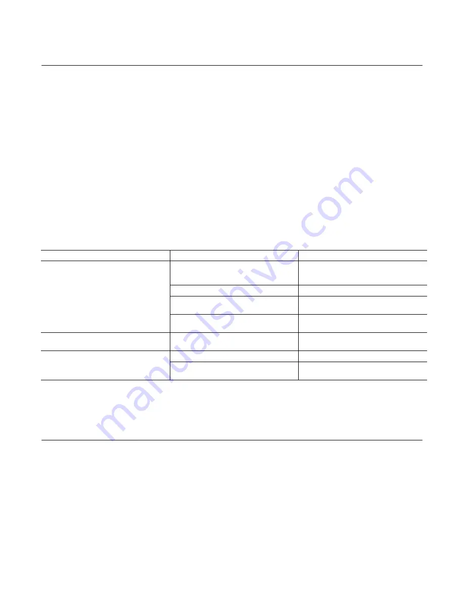
G. Troubleshooting
Table 4 lists the common difficulties experienced with vane
motors and hydraulic systems. It also indicates the probable
causes and remedies for each of the troubles listed.
It should always be remembered that many apparent motor
failures are actually due to the failure of other parts of the
system. The cause of improper operation is best diagnosed
with adequate testing equipment and a thorough understand-
ing of the complete hydraulic system.
TROUBLE
PROBABLE CAUSE
REMEDY
Motor not developing sufficient speed or
torque.
Insufficient fluid pressure.
Check delivery of motor. Make certain
sufficient hydraulic fluid is available to the
motor. Check motor drive speed.
System overload relief valve set too low.
Check pressure and reset relief valve.
Motor requiring excessive torque.
Remove motor and check torque
requirements of drive shaft.
Parts of motor cartridge scored due to
excessive pressure or foreign matter in oil.
Remove motor for overhaul.
Motor shaft continuing to rotate when control
is in
‘
OFF
’
position.
Control valve is not functioning properly.
Check control valve for correct spool and
leakage.
Motor turning in wrong direction.
Improper port connections at valve plate.
Reverse port connections.
Components in system not functioning as
intended.
Check complete system for proper operation.
Table 5. Troubleshooting Chart.
Section VI
–
Overhaul
A. General
Plug all removed units and cap all lines to prevent the entry
of dirt into the system during shutdown. During disassembly,
pay particular attention to identification of the parts for correct
assembly.
Figure 7 is an exploded view which shows the proper
relationship of the parts for disassembly and assembly.
Figure 1 can be referred to for the correct assembled
relationship.
B. Disassembly
Be certain the unit is not subjected to pressure. Disconnect
and cap all lines before removing the motor from its
mounting. Remove the flanges, screws and o-rings from
M2-500 series motors.
1.
Cover End.
Place the motor on blocks cover end up.
Remove the four cover screws and washers and lift off the
cover.
Remove the o-ring from the groove in the cover. Remove the
pressure plate and wave washer from the cover and remove
the o-ring from the pressure plate.
Do not
disassemble the
shuttle valves unless it is necessary to replace them
because of leakage.
Lift off the ring and locating pins. Remove the vanes and
rotor sub-assembly.