


5
Section III
–
Principles of Operation
A. General
Rotation of the motor shaft is caused by fluid flow
through the motor exerting a force against the vanes.
This force is in effect tangential to the rotor and causes
the rotor to turn, carrying the motor shaft with it.
If fluid is directed into the motor from the body port (see
Figure 2), shaft rotation, as viewed from the head end, is
counterclockwise. When the cover port is used for the inlet,
rotation clockwise as viewed from the cover end. Changing
the direction of fluid flow thus changes the direction of motor
rotation. This is usually accomplished by the use of a
suitable directional control valve. With either port open to
pressure, the other port becomes the return port.
As viewed from cover end:
Rotation is counterclockwise when body port is inlet.
Rotation is clockwise when cover port is inlet.
ÂÂÂ
ÂÂÂ
ÂÂÂ
ÂÂÂÂÂ
ÂÂÂÂÂ
ÂÂÂÂÂ
ÂÂÂÂÂ
ÂÂÂÂÂ
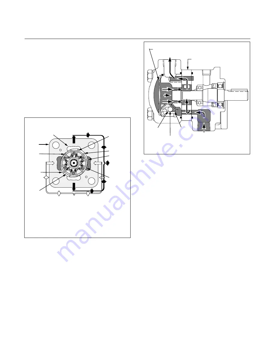
Kidney Slot
Cover End View
Ring
Vane
Rotor
From Body Port
To Cover
Port
1
2
3
4
9
A
A1
B
B1
Figure 2.
B. Cartridge Action
High pressure oil entering the body port (see Figure 3) is
divided by internal coring and is directed into chambers
between the vanes through kidney slots A and A1 (see
Figure 2). The chambers between vane 2 and vane 3 are
supplied with high pressure oil from port A. The chambers
between vane 3 and vane 4 are at a lower pressure because
they are open to discharge port B. Counterclockwise rotation
of the rotor and vane assembly results from the difference in
pressure across vane 3. This action is duplicated on vane 9.
As any two successive vanes pass the A and A1 slots,
fluid between them is trapped and carried to the B and
B1 slots. Here, the distance between the rotor and ring
is decreasing, and the fluid flows into low pressure
kidney slots and is directed through internal coring to
tank.
ÄÄÄ
ÄÄÄ
ÄÄÄ
ÄÄÄ
Wave Washer
Cover
Drive Cartridge
Seat
Seat
Body
Shuttle
Valve
Figure 3.
It can be readily seen from Figure 2 that if the direction
of flow is reversed, B and B1 will become pressure
chambers and the direction of shaft rotation will be
reversed.
C. Hydraulic Balance
Regardless of whether A and A1 or B and B1 are high
pressure chambers, equal pressure will always be present in
any two chambers 180 degrees apart. Thus, hydraulic loads
against the shaft cancel each other out and the unit is in
hydraulic balance.
D. Rocker Arms
Rocker arms (Figure 4) are required to hold the vanes
outward against the ring until system pressure builds up.
They also aid in keeping the vanes against the ring when the
pressure is at a high level (see
E. Pressure Plate
below).
These arms move about a pivot pin attached to the rotor. The
ends of each arm support tow vanes 90 degrees apart.
Action is such that as one vane (A) is being forced into its
rotor slot by the ring, the other (B) is forced out by the rocker
arm. Although the arm exerts a certain amount of spring
tension against the vanes, flexing is virtually eliminated by
the rocking action as the arm swivels on its pin.
E. Pressure Plate
The pressure plate serves two purposes. It seals the cover
end of the cartridge against internal leakage and it contains
porting to feed system pressure to the base of the vanes to
hold them out against the ring.