


8
2.
Viscosity Index
–
Viscosity index reflects the way
viscosity changes with temperature. The smaller the viscos-
ity change the higher the viscosity index. The viscosity index
of hydraulic system oil should not be less than 90. Multiple
viscosity oils, such as SAE 10W-30, incorporate additives to
improve viscosity index (polymer thickened). Oils of this type
generally exhibit both temporary and permanent decrease in
viscosity due to the oil shear encountered in the operating
hydraulic system. Accordingly, when such oils are selected, it
is desirable to use those with high shear stability to insure
that viscosity remains within recommended limits.
3.
Additives
–
Research has developed a number of
additive agents which materially improve various characteris-
tics of oil for hydraulic systems. These additives are selected
to reduce wear, increase chemical stability, inhibit corrosion
and depress the pour point. The most desirable oils for
hydraulic service contain higher amounts of antiwear
compounding.
Special Requirements
Where special considerations indicate a need to depart from
the recommended oils or operating conditions, see a Vickers
sales representative.
Cleanliness
Clean fluid is the best insurance for long service life. To
insure your hydraulic system is clean, perform the following
steps.
1. Clean (flush) entire system to remove paint, metal
chips, welding shot, etc.
2. Filter each change of oil to prevent introduction of
contaminants into the system.
3. Provide continuous oil filtration to remove sludge and
products of wear and corrosion generated during the life of
the system.
4. Provide continuous protection of system from entry of
airborne contamination, by sealing the system and/or by
proper filtration of the air.
5. Proper oil filling and servicing of filters, breathers,
reservoirs, etc., cannot be overemphasized.
6. Good system and reservoir design will insure that
aeration of the oil is kept to a minimum.
F. Overload Protection
A relief valve must be installed in the system to limit pressure
to a prescribed maximum. This protects the system
components from excessive pressure. The setting of the
relief valve depends on the work requirements of the system
and the maximum pressure ratings of the system
components.
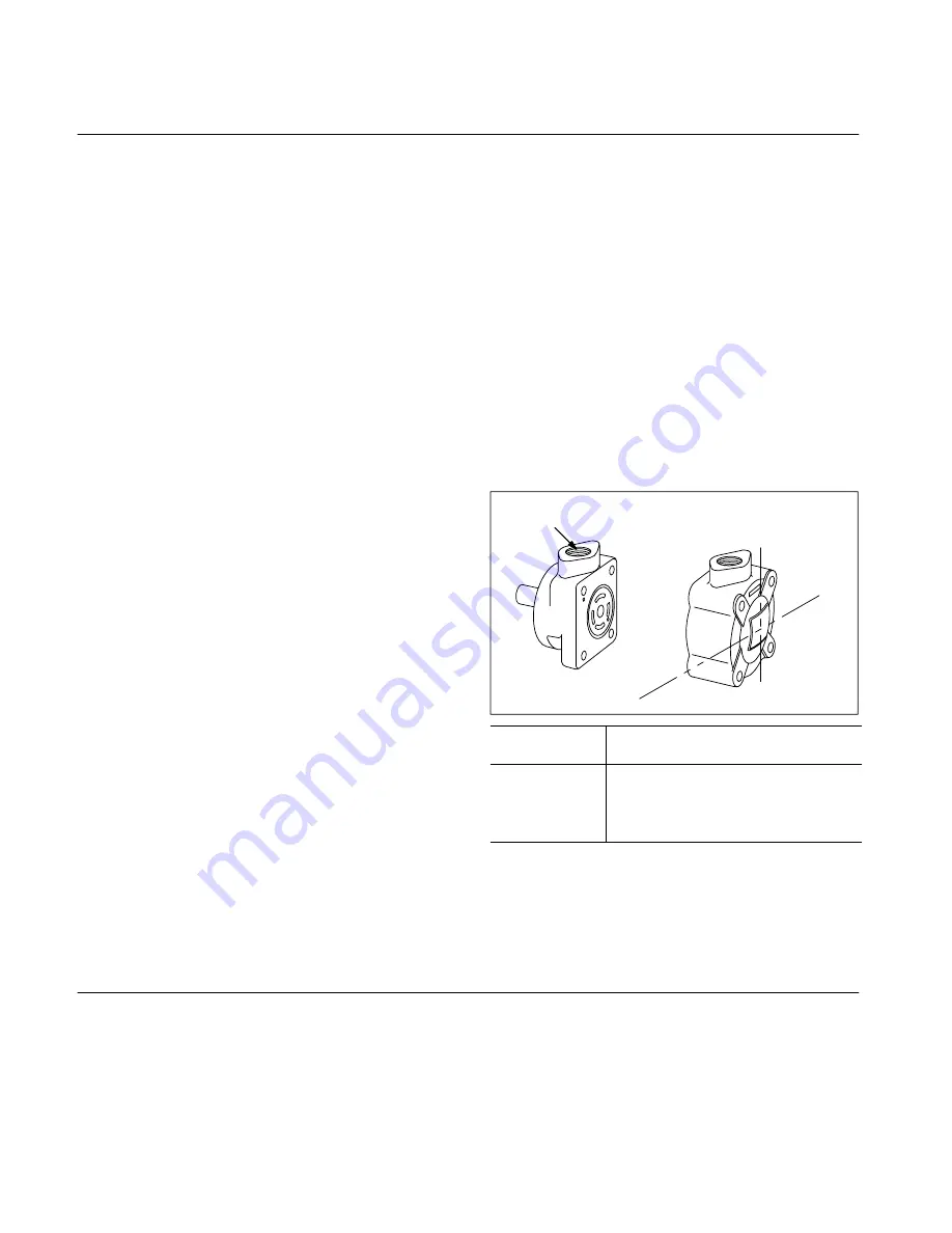
G. Port Positions
Covers can be assembled in four positions with respect to
bodies as shown in Figure 6. To change the relative location
of the ports, it is necessary only to remove the four cover
bolts and rotate the cover to the desired position. Cover bolts
must be tightened to the torque specified in Figure 7 at
reassembly.
A
B
C
D
Body
Port
Model Code
Cover Port Position
(viewed from cover)
A
B
C
D
Opposite body port
90
_
clockwise from body port
In line with body port
90
_
counterclockwise from body port
Figure 6.
Section V
–
Service, Inspection and Maintenance
A. Service Tools
No special tools are required to service these units.
B. Inspection
Periodic inspection of oil condition and tubing connections
can save time-consuming breakdowns and unnecessary
parts replacement. The following should be checked
regularly.
1. All hydraulic connections must be kept tight. A loose
connection in a pressure line will permit the fluid to leak out.
Loose connections in other lines can permit air to be drawn
into the system, resulting in noisy and/or erratic operation.
2. Clean fluid is the best insurance for long service life.
Therefore, the reservoir should be checked periodically for
dirt or other contaminants. If the fluid becomes contaminated,
the system should be thoroughly drained and the reservoir
cleaned before new fluid is added.