background image


10

PA/GA Power Management unit

SONIX Pm10 TECHNICAL mANUAL  

TM365-1 / A  June 2022  www.eaton.com

4.4  48 V dc power distribution

48 V dc power is generated internally by an ac to dc 

power supply, switched live between the power inputs. 

The output voltage is regulated to +/- 0.5% and is used 

for all PA/GA system dc power needs. Total load should 

not exceed 95W.

Current limit for individual 48 V dc output is 2 A, 

protected by replaceable fuse located on the front panel 

(see Figure 1).

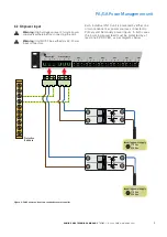
When more than one Pm10 unit is being used in the 

system, their 48 V dc rail can be shared between the 

units. To achieve this, the Pm10 units DC outputs 

are daisy-chained: 48 V dc output of the first unit is 

connected to 48 V dc input of the next unit, with no limit 

on how many units can be chained. The 48 V dc output 

from the last unit is then used as a primary power 

source for PA/GA 48 V dc with the others providing a 

redundant supply

.

Warning:

 If utilising the 48 V output in user 

touchable equipment an isolating DC:DC power 

supply is required.

O/P 1

O/P 2

O/P 3 

O/P 4

O/P 5

L

+

N

+

E

L

+

N

+

E

L

+

N

+

E

L

+

N

+

E

L

+

N

+

E

Power Bus


O/P 1

O/P 2

O/P 3 

O/P 4

O/P 5

L

+

N

+

E

L

+

N

+

E

L

+

N

+

E

L

+

N

+

E

L

+

N

+

E

Power Bus


48 v dc Output

to PA/GA rack

Sonix Pm10

#2

Sonix Pm10

#1

Warning: Dangerous voltages. Do not open

Warning: Dangerous voltages. Do not open

Fault

O/P

N/C com

48VDC

O/P

+     -

48VDC

I/P

+     -

Fault

O/P

N/C com

48VDC

O/P

+     -

48VDC

I/P

+     -

Figure 12. 48 V dc power distribution between two Pm10 units.

ote: 

N

These cables are power feeds. They should be, where 

possible, routed within the PA/GA system in a separate way to avoid 

contact with ac power or audio cables and reduce the possibility of 

interference.

Maximum supported wires are:

• 

Solid: 


    1.5 

mm

2

• 

Stranded:  

• 

including sleeved ferrule: 


0.5 mm

2

• 

including non-sleeved ferrule:  

1.5 mm

2

Summary of Contents for SONiX Pm10

Page 1: ...SONIXTM Pm10 Power Management Unit SonixTM Pm10 Technical Manual...

Page 2: ...3 3 2 Power and utility 5 3 3 3 Environmental operating conditions 5 4 INSTALLATION AND CONNECTIVITY 6 4 1 Physical installation 6 4 2 Power Bus 7 4 3 AC power input 9 4 4 AC power output 7 4 4 1 Out...

Page 3: ...O REDUNDANT POWER SUPPLIES 11 FIGURE 9 PM10 POWERED FROM A SINGLE POWER SUPPLY 12 FIGURE 10 CONNECTING SONIX 350 D TO THE OUTPUTS 13 FIGURE 11 AUXILIARY OUTPUT 13 FIGURE 12 48 V DC POWER DISTRIBUTION...

Page 4: ...failure or dangerous fluctuations the system will automatically switch over to the standby power supply Even under full load operation this is achieved without any disruption to the system operation...

Page 5: ...dary Supply Power Bus Fault O P N C com 48VDC O P 48VDC I P COMPLIANT 8 7 6 5 4 3 2 1 Warning Dangerous voltages Do not open Power Bus Sync Beacon Bus Global Bus Amp Bus HMi Bus HMi Bus I O Bus 48V DC...

Page 6: ...althy Fault Healthy Fault Healthy Fault Healthy Fault Healthy Fault Healthy Fault Sonix Pm10 Volts Amps Rack DC Primary Secondary Healthy Fault Healthy Fault 7 6 5 4 3 2 1 O P 1 O P 2 O P 3 O P 4 O P...

Page 7: ...individual Pm10 unit is powered by either one or two redundant ac power sources connected to Primary and Secondary power inputs In both cases the incoming power feed must be protected by at least one...

Page 8: ...rth ote N As these cables are power feeds they should be where possible routed within the PA GA system in a separate way to avoid contact with dc power or audio cables and reduce the possibility of in...

Page 9: ...60Hz AC Input 85 265 vac 50 60Hz AC Input 85 265 vac 50 60Hz AC Input 85 265 vac 50 60Hz Sonix 350 d Sonix 350 d Sonix 350 d Sonix 350 d Sonix Pm10 Healthy Fault Healthy Fault Healthy Fault Healthy F...

Page 10: ...c output from the last unit is then used as a primary power source for PA GA 48 V dc with the others providing a redundant supply Warning If utilising the 48 V output in user touchable equipment an is...

Page 11: ...ximately 10 seconds before clearing after any fault has cleared to allow any transient faults to be registered by any external monitoring ote N There is no configuration option to change the sense of...

Page 12: ...n Pm10 reports the status of its outputs via pairs of green and red LEDs grouped with each output see Figure 1 as per table below LED Name Green Red Status Output 1 8 Aux Output On Off Output healthy...

Page 13: ...ing or testing check that Unit is correctly earthed Connection of each cable to and from the system is correct and the cables are not damaged DC input and output ports have the correct polarity There...

Page 14: ...Eaton and SONIX are registered trademarks All other trademarks are property of their respective owners Changes to the products to the information contained in this document and to prices are reserved...

Reviews: