


6
PA/GA Power Management unit
SONIX Pm10 TECHNICAL mANUAL
TM365-1 / A June 2022 www.eaton.com
4 Installation and connectivity
4.1 Physical installation
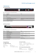
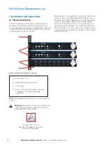
The unit is designed to be fitted inside the industry
standard 19” enclosure, fixed with appropriate size
screw. Depending on the rack and cage nuts used, they
can be either M5 or M6 fitted through four mounting
holes provided on the front panel.
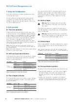
Stacking units is allowed with no additional restrictions,
while still observing the general PA/GA design rules.
The most common configuration is placing Sonix 350-
d units (supported by shelves if rack setup permits)
directly over the Pm10. The unit can self-support on
the front panel mountings but if combined with Sonix
350-d amplifiers in a stack, due to the amplifier weight,
it will require to be installed on shelves or other weight
support structure.
A – Rack frame – 19”
B – Additional Sonix PA/GA units
C – Unit fixings
D – Shelf or other weight support structure.
Compulsory for units supporting
amplifiers.
TM
R
Healthy Fault
Healthy Fault
Healthy Fault
Healthy Fault
Healthy Fault
Healthy Fault
Healthy Fault
Output 1
Healthy Fault
Output 2
Output 3
Output 4
Output 5
Output 6
Output 7
Output 8
Sonix Pm10
Volts
Amps
Output
Rack DC
Primary
Secondary
Healthy Fault
Output
Aux
Healthy Fault
7
6
5
4
3
2
1
O/P 1
O/P 2
O/P 3
O/P 4
O/P 5
O/P 6
O/P 7
O/P 8
O/P Aux
L
+
N
+
E
L
+
N
+
E
L
+
N
+
E
L
+
N
+
E
L
+
N
+
E
L
+
N
+
E
L
+
N
+
E
L
+
N
+
E
L
+
N
+
E
L
+
N
+
E
L
+
N
+
E
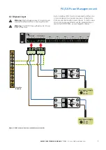
Primary Supply
Secondary Supply
Power Bus
Fault
O/P
N/C com
48VDC
O/P
+ -
48VDC
I/P
+ -
COMPLIANT
8
7
6
5
4
3
2
1
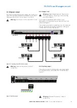
Warning: Dangerous voltages. Do not open
Power Bus
Sync
Beacon Bus
Global Bus
Amp Bus
HMi Bus
HMi Bus
I/O Bus
48V
DC
I/P
+ -
Fault
O/P
N/C
Com
Default
Config
COMPLIANT
Healthy Fault
Healthy Fault
Healthy Fault
Healthy Fault
Healthy Fault
Healthy Fault
Healthy Fault
Output 1
Healthy Fault
Output 2
Output 3
Output 4
Output 5
Output 6
Output 7
Output 8
Output 8
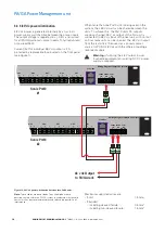
STATUS
Power
Amp
Earth
Line
Fan
Overload/
Shutdown
Temp
hsb
Audio Output
Power
Amp
Earth
Line
Fan
Overload/
Shutdown
Temp
hsb
Audio Output
STATUS
A
C
B
D
!
!
Figure 3. Stacking Pm10 with other Sonix units.
ote:
N
Recommended fixing screw length is 16 mm, complete with
washers.
Warning:
Ensure that no ventilation points are
obstructed, and that the module is correctly
supported within the cabinet.
IEC 60417-6043 (2011=01)
Beware of sharp edges and corners!
Take care while handling.