


1
1
1
1
1
1
1
1
1
1
1
1
1
1
1
1
1
1
1
1
1
1
1
1
1
1
1
1
1
1
5
PA/GA Power Management unit
SONIX Pm10 TECHNICAL mANUAL
TM365-1 / A June 2022 www.eaton.com
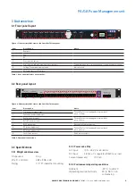
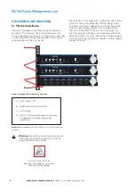
3 Unit overview
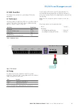
3.1 Front panel layout
Figure 1. General, simplified view of the Sonix Pm10 front panel.
Item
Description
Notes
1
8 outputs
2
Aux
3
DC
4
User selection button
5
User selection and measurements status indicator
Toggles between user’s selection and unit’s automatic measurements
6
Voltage/Current measurement value
Indication only
7
AC Power input health indicator
Table 1. Front panel indicators and switches.
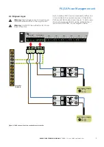
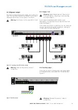
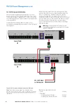
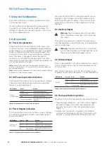
3.2 Rear panel layout
Figure 2. General, simplified view of the Sonix Pm10 rear panel.
Item
Description
Notes
1
Primary power supply input
Phoenix Contact 3-way pluggable terminal block
pitch: 10.16 mm
2
Secondary power supply input
3
Auxiliary power output
Phoenix Contact 3-way pluggable terminal block
pitch: 7.62 mm
4
8 off AC power outputs
5
RJ45 connections
Reserved for future expansion
6
DC power supply input
Phoenix Contact 2-way pluggable terminal block
pitch: 3.81 mm
7
DC power supply output
8
Fault status contact
Relay contact outputs
Table 2. Rear panel connections.
TM
R
Healthy Fault
Healthy Fault
Healthy Fault
Healthy Fault
Healthy Fault
Healthy Fault
Healthy Fault
Output 1
Healthy Fault
Output 2
Output 3
Output 4
Output 5
Output 6
Output 7
Output 8
Sonix Pm10
Volts
Amps
Output
Rack DC
Primary
Secondary
Healthy Fault
Output
Aux
Healthy Fault
7
6
5
4
3
2
1
O/P 1
O/P 2
O/P 3
O/P 4
O/P 5
O/P 6
O/P 7
O/P 8
O/P Aux
L
+
N
+
E
L
+
N
+
E
L
+
N
+
E
L
+
N
+
E
L
+
N
+
E
L
+
N
+
E
L
+
N
+
E
L
+
N
+
E
L
+
N
+
E
L
+
N
+
E
L
+
N
+
E
Primary Supply
Secondary Supply
Power Bus
Fault
O/P
N/C com
48VDC
O/P
+ -
48VDC
I/P
+ -
COMPLIANT
8
7
6
5
4
3
2
1
Warning: Dangerous voltages. Do not open
Power Bus
Sync
Beacon Bus
Global Bus
Amp Bus
HMi Bus
HMi Bus
I/O Bus
48V
DC
I/P
+ -
Fault
O/P
N/C
Com
Default
Config
COMPLIANT
Healthy Fault
Healthy Fault
Healthy Fault
Healthy Fault
Healthy Fault
Healthy Fault
Healthy Fault
Output 1
Healthy Fault
Output 2
Output 3
Output 4
Output 5
Output 6
Output 7
Output 8
Output 8
STATUS
Power
Amp
Earth
Line
Fan
Overload/
Shutdown
Temp
hsb
Audio Output
Power
Amp
Earth
Line
Fan
Overload/
Shutdown
Temp
hsb
Audio Output
STATUS
A
C
B
D
!
!
3.3 Specifications
3.3.1 Weight and dimensions
Un-packed:
2 kg
W x D x H (mm):
482 x 306 x 43
Fixing:
1U 19” industrial mounting
3.3.2 Power and utility
AC Input:
100 – 250 V ac 50-60 Hz
DC Input:
48 Vdc ±1% regulated, 95W max. load
Current (quiescent):
100 mA
3.3.3 Environmental operating conditions
Ambient:
-20 °C to +55 °C
Operating relative humidity:
20 to 95 % non-
condensing