


80 kVA - 130 kVA UPS
User’s and Installation Manual
1017397
Revision D (update)
27
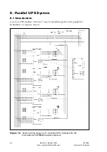
7. User’s guide to operations
This chapter contains the necessary information on how to use the UPS.
The control panel informs the user the status of the UPS, measurements, alarms and
history log. It is also used to controlling and configuring the UPS with the function
buttons underneath the display.
During commissioning the manufacturer representative will train the users to operate
the UPS system.
7.1 Graphical Control panel
The monitor panel shows the status of UPS operation with five LED indicators and with a
LCD screen. The display also generates audible alarm if the user should be alerted.
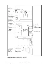
Figure 13.
Control panel with the main screen
LED indicators
This green LED is lit when there is voltage at the output terminals and
when the UPS is in normal or static bypass mode.
This yellow LED is lit when the UPS is operating in battery mode.
This yellow LED is lit when UPS is on and is operating in bypass mode.
This yellow LED is lit when there is an active notice that doesn’t require
immediate action.
This red LED is lit when there is an active alarm that requires immediate
action.
There are five pushbuttons underneath of the LCD display that are used to access the
menu structure.


