


80 kVA - 130 kVA UPS
User’s and Installation Manual
1017397
Revision D (update)
16
5.4 Power connections
The electrical planning and the UPS installation must be done by qualified personnel only.
All power connections shall be done with cable lugs.
WARNING!
The UPS contains high voltage and current which can injure or kill personnel and
damage equipment.
The customer has to supply the wiring to connect the UPS to power lines.
The installation inspection and initial start up of the UPS and extra battery cabinet
must be carried out by a service engineer from the manufacturer or from an agent
authorised by the manufacturer.
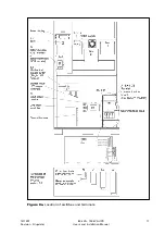
The UPS unit has the following power connections:
•
3-phase and
connection for rectifier input (also in IGBT model a non-
functional termination point for the neutral wire, if provided)
•
3-phase and N and
connection for bypass input
•
3-phase and N and PE connection for load output
•
+, - and PE connection for batteries
All input and output wiring of the UPS connects to the terminals located behind the
cover plates behind the doors. Wiring can be routed through the cable entry at the
bottom of the UPS cabinet.
The UPS is provided with two single phase L-N power outlets. Connections are at
terminals X5 (IGBT model only). These power supplies are protected with automatic 10
A fuses F14 and F15 (IGBT model only), see figure 8a.
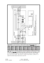
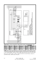
Figure 7.
An IGBT 80-130 kVA UPS battery connections to the battery breaker F1
when cable entry from A) bottom B)top.
Note!
Change of jumper position in battery breaker F1. Do not change internal cabling.
See figure 7.