Eaton OnGuard Installation Manual Download Page 7

ONGUARD COMMAND CONSOLE INSTALLATION MANUAL

         www.eaton.com/onguard

7

OnGuard Command Console

Installation Manual

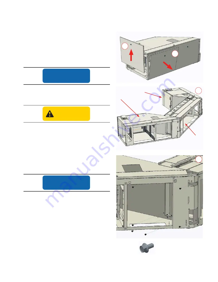
A. Assemble the Base Cabinets

1�  Unlock and remove rear panels from each of the base 

cabinets� To remove a panel, open rear cable channel 
cover, and pull panel off from top edge�

2�  Unlock and remove the end panels from the left and right 

base cabinets by lifting up on the panels�

3�  Position the three base cabinets as close to their final 

positions as possible 

NOTICE

ONCE COMPLETELY ASSEMBLED, THE CONSOLE WILL 
BE HEAVY AND DIFFICULT TO MOVE, PARTICULARLY ON 
CARPETING.

CAUTION

TO ENSURE ADEQUATE COOLING OF STORED ELECTRONIC 
COMPONENTS, DO NOT PLACE THE REAR OF THE BASE 
CABINETS  CLOSER THAN  3" TO A WALL.

4�  Assemble the left and right base cabinets to center base 

cabinet with (12) 

1

4

" x ½" self-threading hex head screws  

(6 screws for each flank base cabinet)� 

5�  Adjust leveling feet to ensure top of base structure is 

level and aligned�  

NOTICE

DO NOT OMIT ANY SCREWS. ALL SCREWS ARE REQUIRED 
TO ENSURE THAT CONSOLE REMAINS STABLE WHEN WORK 
SURFACE IS ELEVATED TO HIGHEST POSITION.

ALL LEVELING FEET OF BASE STRUCTURE MUST BE IN 
DIRECT CONTACT WITH THE FLOOR TO ENSURE CONSOLE 
REMAINS STABLE WHEN WORK SURFACE IS ELEVATED TO ITS 
HIGHEST POSITION.

IMPROPER ADJUSTMENT OF THE LEVELERS MAY CAUSE THE 
BASE CABINETS TO TWIST, RESULTING IN MIS-ALIGNMENT OF 
FRONT DOORS AND DRAWERS. ENSURE THAT LEVELERS ARE 
ADJUSTED IN SUCH A WAY AS TO ENSURE PROPER DOOR 
AND DRAWER ALIGNMENT.

A x 12

Right Base 

Cabinet

Center Base 

Cabinet

Left Base 

Cabinet

Hardware 

required

A�1

A�2

A�3

A�4

SECTION III - Assembling the Console 

Summary of Contents for OnGuard

Page 1: ...OnGuard Command Console Installation Manual OnGuard Command Console ...

Page 2: ...s revision history February 2017 First Publication Pub No IB210002EN Sales Representative and Contact Information Contact your Eaton Sales representative using one of the methods below Phone Call us toll free at 800 225 7348 US Only or 508 852 4300 Mail Eaton 160 Gold Star Boulevard Worcester MA 01606 Email InfoESWorcesterMA Eaton com Web Visit us at www eaton com onguard and click on Contact Us S...

Page 3: ...ng your console Familiarize yourself with the warning symbols that appear throughout this manual Before You Begin Before installing the OnGuard Command Console it is recommended that you do the following SECTION I OnGuard Command Console Installation Manual DANGER DANGER indicates a hazardous situation which if not avoided will result in death or serious injury WARNING WARNING indicates a hazardou...

Page 4: ...ronment System and personal items DANGER DANGER To reduce the risk of electric shock This console includes two power cords Always fully unplug this console from the electrical outlets before cleaning testing repairing or moving the console WARNING 1 This console is for commercial use only 2 Unplug from outlet before putting on or taking off parts NOTE This console includes two power cords 3 Close ...

Page 5: ... piece worksurfaces combination wrench PERSONAL ENVIRONMENT SYSTEM Optional Flat blade screw driver or 5 16 nut driver for hose clamps Personalprotectiveequipmentrecommended Eye protection Work gloves Steel toe shoes Monitor Pole Track TechTrack Comfort Edge TechCurb Center Base Cabinet Right Base Cabinet RH Worksurface Support Frame Lift Control Box Leveling Feet Bottom Cable Access Left Base Cab...

Page 6: ... wood screw Silver 56 pcs F 8 x Phillips head wood screw Black 14 pcs G Tie bolt Silver 6 pcs packaged with worksurface H Non threaded T washer Silver 6 pcs packaged with worksurface I Threaded T nut Silver 6 pcs packaged with worksurface J 10 x 5 8 Phillips flat head screw Silver 4 pcs K 10 Lock Nut Silver 6 pcs L 5 16 Lock Nut Silver 6 pcs M 1 4 Lock Nut Silver 5 pcs N 1 4 Star Washer Silver 5 p...

Page 7: ... TO A WALL 4 Assemble the left and right base cabinets to center base cabinet with 12 1 4 x 1 2 self threading hex head screws 6 screws for each flank base cabinet 5 Adjust leveling feet to ensure top of base structure is level and aligned NOTICE DO NOT OMIT ANY SCREWS ALL SCREWS ARE REQUIRED TO ENSURE THAT CONSOLE REMAINS STABLE WHEN WORK SURFACE IS ELEVATED TO HIGHEST POSITION ALL LEVELING FEET ...

Page 8: ...ECTION THEN RE TIGHTEN THE BASE CABINET SCREWS AFTER COMPLETING STEP 2 a Partially insert 2 M6 x 14mm Allen head screws into the innermost side of each outer lift motor Leave screws protruding about 1 4 b Place the support frames into position above the outer lift motors As you lower the frames onto the lift motors ensure that the support frame s screw tabs are first inserted into the center works...

Page 9: ...pply cable into the lift control box receptacle Loop the power supply cable into the U shaped strain relief slot on control box Then attach control box to front worksurface stiffener with 2 10 x 1 3 4 self threading screws as shown in figure C 1 2 Route the power cord from the control box into the left support frame channel and then through the center worksurface support frame as shown in figure C...

Page 10: ...he cables into the appropriate numbered receptacles in the control box Motor cable 2 is shown motor cable 3 will follow a similar path through the right support frame 4 Route 2 lift motor cables from the outer lift motors 1 and 4 to the control box plugging the cables into the appropriate numbered receptacles in the control box Motor cable 1 is shown motor cable 4 will follow a similar path throug...

Page 11: ...er cord into a nearby 120 volt AC outlet 2 The lift motor system is initialized by pressing and holding the down button The motors will automatically lower to their bottom most position if not already there then run upwards approx 3 mm and then down again to their lowest position Only release the down button when the movement has completely stopped 3 If the button is released before the sequence i...

Page 12: ...trips onto the edges of the rectangular opening in the center worksurface The flexible tabs on the trim strips should be flush with the decorative writing surface of the worksurface 3 Insert the 2 un notched trim strips onto the edges of the rectangular slots in the left and right worksurfaces The flexible tabs on the trim strips should be flush with the decorative writing surface of the worksurfa...

Page 13: ...NELS TOGETHER BEFORE LIFTING AND POSITIONING THEM 5 Insert 3 tie bolts and 3 non threaded T washers into each outer worksurface 6 Insert plastic splines into the side grooves on each outer worksurface 7 Remove the foam edge protectors then position the worksurface s onto the support frames Ensure that the lift control pad cable sits in the groove in the outer worksurface WARNING AS YOU POSITION TH...

Page 14: ...uired to bring the components into alignment NOTICE DO NOT TWIST OR FORCE THE WORKSURFACE INTO ALIGN MENT WITH THE SUPPORT STRUCTURE THIS CAN BUILD STRESS INTO THE SYSTEM AND AFFECT THE LIFTING ACTION 10 Attach the worksurface to the support structure with Phillips head wood screws 11 Attach the control pad to the worksurface with 2 8 x Phillips head wood screws Retain the cable in the adjacent sl...

Page 15: ... the free end of the 10 foot ground wire through the left cable chain and then to the base cabinet s Protective Earth Terminal PET The PET is indicated with a symbol Refer to section V A for instructions on connecting the ground wire to the Protective Earth Terminal PET 3 Pull the lift motor power cord up through the worksurface opening and into the TechCurb Plug the cord into the closest TechCurb...

Page 16: ...ear corner cover s may be left un installed to enable cable ingress at the corner s 1 Install 2 lower 10 x 3 8 Phillips head self threading screws as shown Leave the screws protruding about 1 16 2 Lower the bottom corner cover onto the two screws engaging the screws it the slots in the cover 3 Secure the cover with two additional top screws 4 Engage the upper corner cover s hooks into the slots an...

Page 17: ... ships with 4 blank module covers and 1 monitor pole module All of the modules simply snap into the grooves in the center TechTrack trim strips Optional Connectivity Module 2 Connectivity modules are available in 4 3 jack and 8 6 jack widths The module accommodates standard low voltage keystone style snap in connectors not included Optional Personal Environment System Outlet Module See section IV ...

Page 18: ...o the TechTrack with the 2 threaded studs protruding through the monitor pole module plate The monitor pole module plate is usually located in the center position tabs on plate will register it in position See figure B Refer to the pole attachment steps in the next section To install a monitor pole 1 Assemble the monitor pole base plate onto the pole with 4 Phillips flat head screws included with ...

Page 19: ...THAT THEYWILL BEAVAILABLETOTHE END USER OFTHE CONSOLE 1 Attach the personal environment system to the underside of the rear worksurface support frame with Tech Curb 4 x 1 2 self threading hex head screws 2 Plug the supplied AC power cord into the unit and then route the cord up into the TechTrack as shown and then into the TechCurb Plug the cord into one of the TechCurb s power strips 3 Run the pe...

Page 20: ... cap To attach a Trillium style light to the bracket 1 Attach the task light support sleeve and two washers to the bracket with a x 1 Allen head screw and a lock nut 2 The light s support stud can now be inserted into the sleeve Follow the instructions provided with the Trillium light to complete the assembly To attach the bracket to the rear of the monitor pole 1 Remove the monitor pole s top cap...

Page 21: ...at right and are the only terminals to which the protective earth ground connections shall be attached When grounding the console to the building common ground ing it is essential that the main protective ground is connected and secured to the terminal first with its own star washer and lock nut before any bonding connections are made on top as shown below B B M x 5 N x 5 Hardware required B Plugg...

Page 22: ...height either in inches or cm The display also shows error codes Adjust the display to show the correct height It may be necessary to adjust the height display after the initial set up of the console Simultaneously press the UP and DOWN arrow buttons or and keep them pressed for 5 seconds This allows the initial height to be re set Until the initial height is re set the display will show three min...

Page 23: ...s the detection is registered only in the display and no message is sent to the control box E01 The console has an unknown position and needs to be initialized See Section III D E02 Overload upwards has occurred E03 Overload downwards has occurred E16 Illegal keys pressed Other diagnostic error codes may get displayed When calling your customer service representative for technical assistance pleas...

Page 24: ...ose connections and pinched or frayed wires Laminated Worksurface Care and Cleaning Avoid placing hot items and heat producing appliances on the worksurface When set directly upon the worksurface hot objects can damage the laminated surface To clean the surface use a damp cloth or sponge and a mild soap or detergent Difficult stains such as coffee or tea can be removed using a mild household indus...

Reviews: