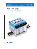
background image

MTL7700 range


Shunt-diode safety barriers

September 2017
INM 7700 Rev 12

Instruction manual

MTL intrinsic safety solutions 

Summary of Contents for MTL7700

Page 1: ...MTL7700 range Shunt diode safety barriers September 2017 INM 7700 Rev 12 Instruction manual MTL intrinsic safety solutions...

Page 2: ...evaluated by MHSA and judged to meet the applicable requirements of Title 30 Code of Federal Regulations Part 18 68 30 CFR Part 18 68 provided that a relevant installation complies with the following...

Page 3: ...tions 7 5 3 Connections to plant earth 7 5 4 Connections to dummy barriers 9 6 MAINTENANCE 9 6 1 General 9 6 2 Routine inspection 9 7 FAULT FINDING 10 7 1 Introduction 10 7 2 Power supply check 11 7 3...

Page 4: ...osure which offers an additional degree of protection appropriate to the area classification c Unless already protected by design this equipment must be protected by a suitable enclosure against i mec...

Page 5: ...e publications are available either from our website www mtl inst com or on request from your local office 2 DESCRIPTION 2 1 Introduction MTL7700 range of fourth generation intrinsically safe shunt di...

Page 6: ...rking barrier locations Supplied with labels in 1m lengths for cutting to size TGL7700 Spare labels for use with TAG57 tagging strips 0 5m strips supplied in sets of 10 IMB57 Tagging strip supports Tw...

Page 7: ...minimum of two c IMB57 tagging strip support 16 0mm minimum of two if specified d ISP7000 insulating spacer 14 7mm minimum of two if specified e ERB57S or O earth rail 8 mm minimum of two mounting bra...

Page 8: ...2 4 1 6 2 Make sure the barriers are of the correct type and polarity as specified in the safety documentation 3 4 1 Make sure all barriers are mounted the right way round and are properly attached so...

Page 9: ...her end of a column of barriers to provide redundancy and to simplify earth testing procedures WARNING Apart from rare occasions when the mounting surface carries the IS earth the ONLY method of provi...

Page 10: ...57 The tagging strip assembly figure 12 identifies the location of individual barriers ensuring that they are replaced correctly after removal for maintenance or testing Once installed the tagging str...

Page 11: ...for specific connections for individual barriers and applications 5 2 3 Bussed Power applications and connections When a number of barriers use a common power supply the optional power link BPL7700 ca...

Page 12: ...e section 4 3 4 an earth conductor normally copper wire with a cross sectional area of at least 4mm2 12AWG must be connected between ETM7 earth terminals located at each end of the rail and the spare...

Page 13: ...the structural earths of any safe area equipment returned separately to the neutral star point This reduces interference problems but is not essential for safety reasons f In general the use of barri...

Page 14: ...systems are relatively simple and their operation is easy to check However when fault finding is necessary it must only be undertaken after checking with plant personnel responsible for safety that i...

Page 15: ...s To overcome this problem the thermocouple circuits can be protected by using an MTL7760ac barrier as shown in figure 21 This permits the thermocouple output to be measured without needing special au...

Page 16: ...however the changeover switch and current selector reduce the need for connection changes d Using a high resistance in series with the barrier gives more stable results and makes it easier to set the...

Page 17: ...itch inputs with line fault detection To verify correct operation proceed as follows a Connect the barrier as shown in figure 30 b With an ohmeter check the status of the output contacts according to...

Page 18: ...050 Vfz x 1 10 11 4 10 5 11 6 7764 12 1k 12 1010 1050 Vfz x 1 10 11 4 10 5 11 6 7767 15 100 150 110 119 Vfz x 1 12 13 6 12 4 13 7 7779 28 300 93 311 333 Vfz x 2 25 9 26 3 26 26 5 7796 26 300 87 311 33...

Page 19: ...sistance Diode Test ve Diode Test ve Terminal Voltage 10 A Terminal Voltage 20mA V mA Min Max Min Max Min Max 7755ac 3 10 300 15 19 Vfd x 3 Vfd x 3 1 2 1 1 8 2 4 7756ac 3 10 300 15 19 Vfd x 2 Vfd x 2...

Page 20: ...end Resistance Diode Test ve Diode Test ve Terminal Voltage 10 A Terminal Voltage 20mA V mA Min Max Min Max Min Max 7787 28 300 93 311 333 Vfz x 2 26 6 27 4 26 7 27 6 7787 ch2 28 0 9V 26 Vfz x 2 26 6...

Page 21: ...hannel switch proximity input Hazardous Area Figure A8 Single channel switch proximity input Hazardous Area Figure A4 2 wire transmitter switch input Safe Area 3 4 1 2 MTL7789 7 8 5 6 Power 26 6V Powe...

Page 22: ...mV Sense Figure A13 Strain gauge bridges Hazardous Area Safe Area 3 4 1 2 MTL7745 5 6 620 10k 22 9 30V LFD COM CH 1 Power Bus Figure A10 Single channel switch proximity input with Line Fault Detect H...

Page 23: ...1 47 78 0 471 b 1 41 0 34 29 0 942 c 0 125 1 15 39 0 942 MTL7767 a1 a2 0 58 1 45 66 0 56 b 0 58 0 32 22 1 125 MTL7778 ac a1 a2 0 083 16 107 0 33 b 0 083 3 05 4 2 42 0 33 MTL7779 a1 a2 0 083 3 05 4 2 5...

Page 24: ...ndia No 36 Nehru Street Off Old Mahabalipuram Road Sholinganallur Chennai 600 119 India Tel 91 0 44 24501660 24501857 Fax 91 0 44 24501463 E mail mtlindiasales eaton com ITALY MTL Italia srl Via San B...

Reviews: