34
New generation IZM97, 99 low voltage air circuit breaker instruction manual
MN013010EN February 2020 www.eaton.com.cn
Section 4: Accessory devices
Screw
labeling
Shunt trip
disconnect
switch
Slide forward
Lock
Hook foot
Mounting panel
Shunt trip
Slide forward
Lock
Hook foot
Mounting panel
First shunt trip
mounting location
IZM9 low-voltage circuit breaker shunt trip
WARNING
(1) Only qualified electrical personnel should be permit-
ted to work on the equipment.
(2) Always de-energize primary and secondary circuits
if a circuit breaker cannot be removed to a safe work
location.
(3) Drawout circuit breakers should be levered (racked)
out to the DISCONNECT position.
(4) All circuit breakers should be switched to the OFF
position and mechanism springs discharged.
Failure to follow these steps for all procedures described
in this instruction leaflet could result in death, bodily
injury, or property damage.
Section 1: General information
The shunt trip opens the circuit breaker when its coil is
energized by a voltage signal. To replace the shunt trip, it is
necessary to replace the shunt trip and disconnect switch at
the same time.
Section 2: Installation of shunt trip
Proceed with the following 8 steps to install the shunt trip:
Step1: Remove the inner hexagonal mounting screws (four
for 3 pole breakers and six for 4 pole breakers) from the
circuit breaker’s front cover using a 10 mm 1/4-inch socket
wrench. Then pull down on the charging handle (by about
45° angle) to remove the front cover.
Step 2: Attach the corresponding label under “Accessories”
on the cover nameplate.
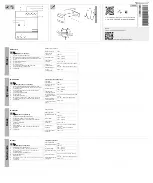
Figure 1. Step 1 and 2
Figure 2. Step 3
Figure 3. Step 4
Step 3: Each shut trip contains a disconnect switch. To install
a disconnect switch, move the lock to the “unlocked” posi-
tion. Install the hook foot into the slot as shown, and slide
the disconnect switch forward to make the hook foot fully
fit into the mounting panel slot. Then, move the lock into the
“locked” position.
Step 4: Move the lock on the shunt trip to the “locked”
position, install the hook foot into the slot, and slide the trip
unit forward to make the hook foot fully fit into the mounting
panel slot. Then, move the lock to the “locked” position.