background image

2

Ronis key interlock  

IZM-KLP-SO-RONIS


eaton corporation

 www.moeller.net/en/support 

08/10 AWA1230-2455

Effective January 2011

Kio paros idtnoificaoiNn

Refer to 

Figurt 1

 for visual identification of the parts listed below:

(A) Interlock arm assembly
(B) HF Securite (Ronis) lock #RBA90GEL3000 with Ronis Protect 

Key (Ronis keylock not supplied)
(C) Bushing
(D) Lock mounting plate
(E) Torsion spring
(F) Interlock adapter assembly
(G) Retainer nut
(H) M3.2 retaining ring
(I) Cable assembly
(J) M3 x 6 self-thread screw (three)
(K) Extension spring
(L) Hex standoff
(M) Trip lever (only used if necessary)

Note:

N

Used only when necessary to replace an existing older design  

trip lever.

(N) Trip lever screw
(P) Adapter plate
(Q) and (R) Standoff mounting screws
(S) Adapter plate screws (two) 

Figurt 1. CNnotnos Nf Kio

(A)

(B)

(C)

(D)

(E)

(F)

(G)

(H)

(I)

(J)

(K)

(L)

(M)

(N)

(P)

(Q)

(R)

(S)

Section 2: installation of key interlock

Proceed with the following 16 steps:

Sotp 1e: 

Remove the front cover of the breaker by loosening four 

mounting bolts (six bolts if four-pole breaker), and hold the charging 

handle down approximately 45 degrees to simplify removal.

Sotp 2e: 

Remove plug from keylock hole. If hole does not exist,  

drill a 1-7/16-inch (36 mm) hole using existing countersink on  

inside of cover as a pilot guide. Use a hole saw, such as a  

Starrett #KAVH0176.

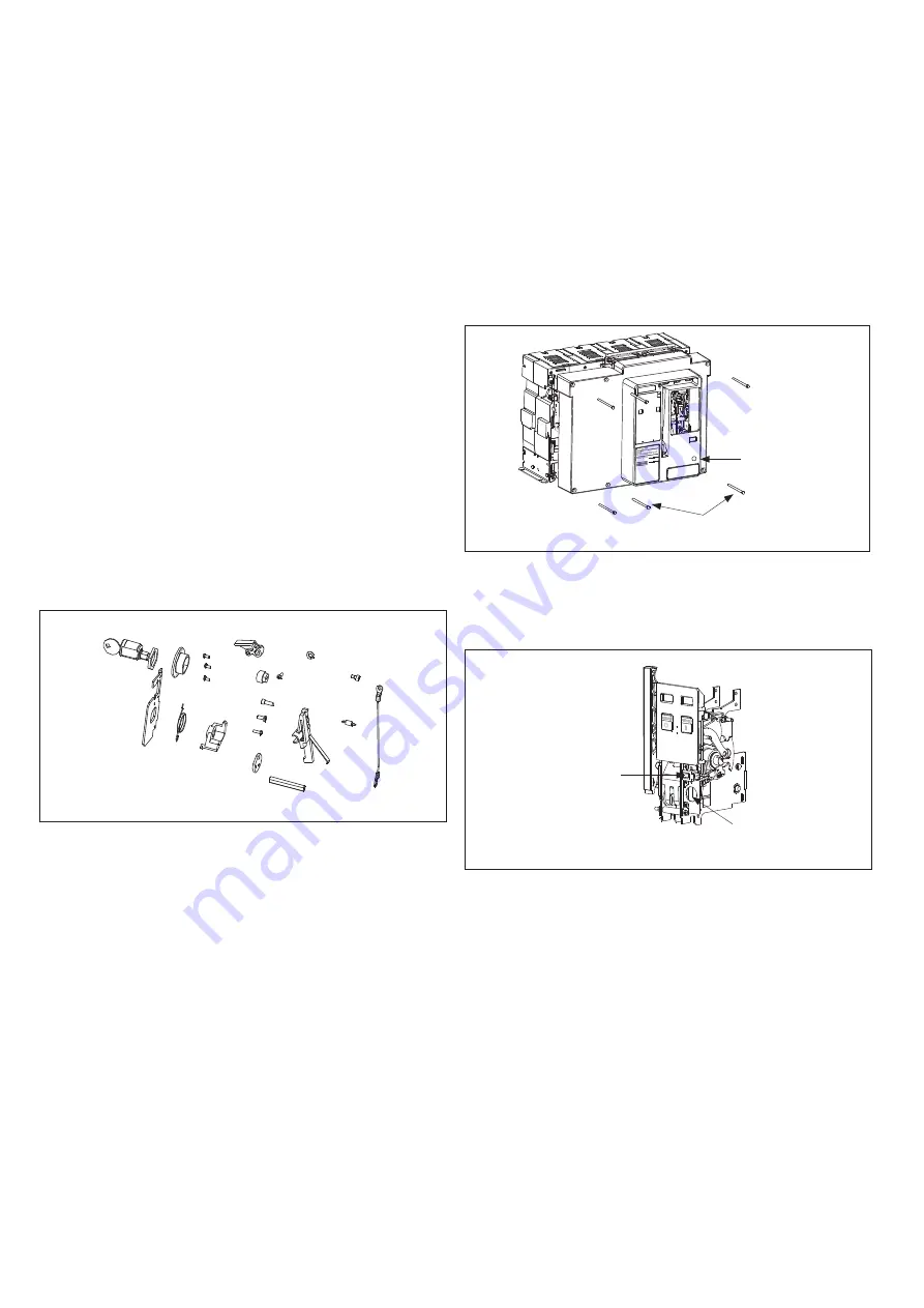
Figurt 2. Sotps 1 and 2

Sotp 3e: 

If there is an operations counter and operation spring 

installed, remove and save these items for later re-installation. 

Remove existing counter/lock mounting plate and discard it. 

Figurt 3. Sotp 3

Key Lock 

Hole Location

Mounting 

Bolts

Operations 

Counter

Mounting 

Plate

Summary of Contents for IZM-KLP-SO-RONIS

Page 1: ...accidentally restarted Verify isolation from the supply Earthing and short circuiting Covering or providing barriers to adjacent live parts Disconnect the equipment from the supply Use only authorized...

Page 2: ...te Q and R Standoff mounting screws S Adapter plate screws two Figure 1 Contents of Kit A B C D E F G H I J K L M N P Q R S Section 2 Installation of key interlock Proceed with the following 16 steps...

Page 3: ...m Assembly A Breaker Swing Arm Metal Spring Arm of Interlock Arm Assembly Fits Behind Breaker Swing Arm Bushing C Hex Nut from Keylock Ronis Lock Mounting Plate D Ronis Keylock B Torsion Spring E Fit...

Page 4: ...crews J Extension Spring K See Detail A Interlock Adapter Tab Step 13 If it is necessary to replace the existing trip lever remove the existing E Clip retaining ring from shaft of mechanism and slide...

Page 5: ...n Gegen Wiedereinschalten sichern Spannungsfreiheit feststellen Erden und Kurzschlie en Benachbarte unter Spannung stehende Teile abdecken oder abschranken Das Ger t ist vom Netz zu trennen Es d rfen...

Page 6: ...und muss vom Kunden zur Verf gung gestellt werden Abbildung 1 Inhalt A B C D E F G H I J K L M N P Q R S Abschnitt 2 Einbau der Abschlie vorrichtung F hren Sie die folgenden Schritte aus Schritt 1 Sc...

Page 7: ...r am Montagearm der Abschlie vorrichtung F hrungsbuchse C Seckskantmutter Ronis Schlo Montageplatte D Ronis Schlo B Sprungfeder E Sprungfeder hier einrasten Schritt 7 Montieren Sie den Adapter der Abs...

Page 8: ...ageplatte J Spannfeder K Siehe Detail A Adapterplatte Abschlie vorrichtung Schritt 13 Sollte es n tig sein den bereits eingebauten Ausl sehebelarm zu ersetzen so entfernen Sie zuerst den Halterring un...

Reviews: