Eaton Durant AMBASSADOR Series Installation And Operation Manual Download Page 26

25

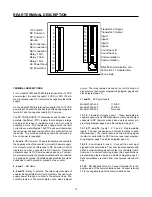
4. Make and break a connection between terminals 4

and 20 using a jumper wire. The main counter and
totalizer should count up each time the connection
makes. If the counters do not count, send the unit to
the factory for repair.

5.  Make and break a connection between terminals 4

and 19 using a jumper wire. The main counter and
totalizer should count down each time the connec-
tion makes. If the counters do not count, send the
unit to the factory for repair.

C. If the counter counted from the manual count source in

step B above, reconnect the sensor and select the
correct dip switch setting. For sensors with a DC pulse
output, perform steps 1 and 2. For magnetic pickup
sensors, proceed to step 3 below.

1. With the sensor output in the high state, measure

the voltage between DC Common and the count
input. The voltage must be greater than 3.5 VDC.  If
it is lower, the sensor is defective, leaky, or is not
compatible with the counter. With current sinking
sensors, try adding a  pull-up resistor (470 ohms to
4700 ohms) from terminal 1 to the count input.
Note: for AC powered counters, the maximum cur-
rent out of terminal 1 must not exceed 100 mA.

2. With the sensor output in the low state, measure the

voltage between DC Common and the count input.
The voltage must be less than 1.9 VDC. If it is
higher, the sensor is defective, leaky, or is not
compatible with the counter. With current sourcing
sensors, try adding a pull-down resistor (220 to
2200 ohms) from the count input to DC Common.

Note: for AC powered counters, the maximum cur-
rent out of terminal 1 must not exceed 100 mA.

3. For magnetic pickup sensors, measure the AC

voltage output of the sensor with the machine
running.  The  output voltage should be greater than
0.45 volts RMS (1.2 volts peak to peak). If it is less,
the sensor is defective, or the target is too far from
the sensor, or the target is not moving fast enough.

III. Error Message On Display:

The message “ERROR” followed by a single digit number on
the display indicates that the counter’s internal self-tests
have detected a problem. See the self-test section of this
manual (page 24) to determine what caused the problem and
how to solve it.

IV. Other Problems:

Other problems are usually caused by programming and/or
wiring errors. Because of the versatility of this counter, it is
impossible to include troubleshooting instructions for every
situation that could arise. However, the following general
troubleshooting steps should help in resolving specific prob-
lems:

1. Define, in detail, exactly  what the problem is and when it

occurs.

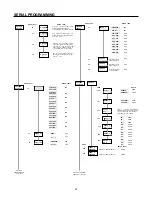
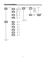
2. Use the block diagram and/or the menu programming

diagram to determine which program options or parame-
ters are related to the problem. Check their setting.

3. Determine which I/O circuits are related to the problem

and check their operation with a voltmeter at the counter’s
terminal strips.

If going through the above 3 steps did not lead you to a so-
lution, perform the following:

1. Record the wiring connections to each terminal on the

unit.

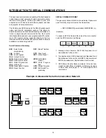
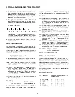
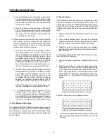
2. Place the unit in the run mode and press the help key.

Write down the 4 lines of data. The Ambassador help
screens are provided as an alternate method of determin-
ing a unit's programming. The two help screens contain
32 characters of information. Pressing the HELP/• key
displays screen 1. The characters are arranged as shown
below:

1

2

3

4

5

6

7

8

16

15

14

13

12

11

10

9

Help Screen Character Numbers - Screen 1

Press the down arrow key to display screen 2.

17 18 19 20 21 22 23 24

32

31

30

29

28

27

26

25

Help Screen Character Numbers - Screen 2

3.

Call the Durant application help line (800-540-9242) and
ask for an application engineer to assist you with trouble
shooting.

TROUBLESHOOTING

Summary of Contents for Durant AMBASSADOR Series

Page 1: ...duction 3 Front Panel Features 4 Run Mode Operation 5 Programming 12 Scale Factors 13 Rear Terminal Description 15 Wiring 18 Serial Communications 24 Diagnostics and Troubleshooting 26 Specifications...

Page 2: ...hod eventtimemeasure ment and can calculate and scale the rate so that even a low count speed 1 Hz can yield accurate rates in engineering units ft sec gal min etc The rate feature operates simulta ne...

Page 3: ...et output The main counter counts in the opposite direction if it is programmed to reset to preset BATCH COUNTER Counts up when main counter reaches the main preset Every two milliseconds the batch co...

Page 4: ...ues Reset Clear Key In the run mode this key can be programmed to reset count values In the preset editing mode this key zeros pre sets that are being changed In the program mode it zeros numeric data...

Page 5: ...formation to the operator and does not affect the operation of the control If power is removed and restored the unit will power up with the display that was last selected RUN MODE MENUS The keystroke...

Page 6: ...rn to the last run mode menu ENTERING THE PROGRAM MODE Press OVERVIEW OF MAIN MENUS Select count mode reset to zero or reset to preset and auto recycle op erations Select the input function to be per...

Page 7: ...igit HELP programs decimal point SEL selects decimal point position HELP SEL selects decimal point position HELP Select Count Input mode using the UP and DOWN cursors to scroll thru this menu CONTACT...

Page 8: ...INPUT 1 STOP CNT INPUT 1 LOCK PGM INPUT 2 DISABLED INPUT 3 DISABLED INPUT 4 DISABLED Output Control Reset Counter Edge triggered Reset Counter Level sensitive Reset Batch Edge triggered Reset Totaliz...

Page 9: ...1 D0 Drop Outoutput Enter output pulse time XX XX seconds SEL SEL SEL MAIN MENU SUB MENU VIEW MENU EDIT MENU Selection repeats as for P1 above Selection repeats as for P1 above Selection repeats as fo...

Page 10: ...KIP or SEND for each data block to be transmitted when requested by the host computer RST KEY DISABLED USER PROGRAM SEL PROGRAM OPTIONS SEL RST KEY DISABLED RST KEY RS C EDG RST KEY RS C LVL RST KEY R...

Page 11: ...als SOLID ST C x2 DIR same as above except counts occur on both edges of input signal for increased resolution RESET TO ZERO the main counter resets to zero when a main counter reset occurs The normal...

Page 12: ...nd transistor output 2 sub menus SERial PORT SER PORT ID enter the desired two digit serial ID number DESCRIPTION OF PROGRAM OPTIONS 00 99 decimal All communications to the control must contain this n...

Page 13: ...the count scaler required to indicate material usage in 1 100 s of feet XXXX XX 100 CS 0 83333 120 Select the XXXX XX position on the counter decimal point menu RATE SCALING The 1 Tau rate meter calc...

Page 14: ...C Common when picked up For maxi mumnoiseimmunity thegroundterminalmustbeconnected to a good earth ground All shielded signal cables should be connected to earth ground or ground on the counter 5 6 an...

Page 15: ...nput signal On input B requires a current sourcing input signal Switch 3 Input A threshold level Off high threshold level use with DC sensors On low threshold level use with mag pickups Turn switch 1...

Page 16: ...act Count Input 1 12 2 3 4 5 6 7 8 9 10 11 13 14 15 16 17 18 19 20 21 22 Dotted lines indicate which inputs may be wired in this manner Typically a separate sensor is used for each input Control input...

Page 17: ...d in the same manner Do not connect Term 1 if sensor is powered from another power supply Wire colors shown correspond to Cutler Hammer inductive proximity and photo sensors Dip switches 1 and or 2 ON...

Page 18: ...or a single channel encoder All dip switches OFF This wiring example shows the load being controlled from the normally open contacts of Relay 1 Wiring for the normally closed contacts 8 9 would be don...

Page 19: ...I code with the RS 485 serial specifi cation and Opto 22 compatible protocol This allows bi directional communications and addressing of multiple con trols on a single two wire communication bus Each...

Page 20: ...ERIAL COMMAND RESPONSE FORMAT responds by sending an ASCII N not acknowledged followed by a one character error code and a carriage return Error Codes 00 Power up Error When power is applied to the un...

Page 21: ...store lock commands when power is removed The host must re issue the desired lock command after power is re applied Lock inputs are not affected by serial lock commands If both a lock input and a seri...

Page 22: ...by a two or three digit number representing the desired sub menu see diagram on pages 22 and 23 for sub menu numbers The counter responds by transmitting a number representing the current option selec...

Page 23: ...102 103 104 105 106 107 108 RESET TO AUTO CYC ZERO P1 DISABLED P1 0 11 12 110 111 120 121 INPUTS PROGRAM INPUT 1 INPUT 2 INPUT 3 INPUT 4 Next item is PROGRAM SER PORT on next page OUT MODE PROGRAM RE...

Page 24: ...ATE SER PORT ID BAUD PARITY Tx DELAY 0 002 0 100 SEND SKIP SEND SKIP SEND SKIP SEND SKIP SEND SKIP READ RPI 40 41 42 43 50 51 52 53 54 410 411 412 413 420 421 422 430 431 500 501 530 531 510 511 520 5...

Page 25: ...ess the front panel reset key This will reset all user programmable options to the factory default settings and rerun all tests 3 If the same error occurs again there is a malfunction within the count...

Page 26: ...ts peak to peak If it is less the sensor is defective or the target is too far from the sensor or the target is not moving fast enough III Error Message On Display The message ERROR followed by a sing...

Page 27: ...eed Mode Solid state Contact Inp A Inp B high speed low speed Add Sub 20 kHz 40 Hz Add Add 20 kHz 40 Hz Count Direction 15 kHz 40 Hz Count x 2 Direction 7 5 kHz N A Quadrature 6 5 kHz N A Quadrature x...

Page 28: ...xx Medium Duty single channel Shaft Encoder 38151 xxxx Medium Duty quadrature Shaft Encoder 48370 xxxx Heavy Duty single channel Shaft Encoder 48371 xxxx Heavy Duty quadrature Shaft Encoder ES9513 RS...

Page 29: ...posed upon any person pursuant to the Magnuson Moss WarrantyAct P L 93 637 asnowineffectorasamendedhereafter The warranties and remedies provided for herein are available to Buyer and shall not extend...

Page 30: ...Printed in U S A Durant 901 South 12th Street Watertown WI 53094 920 261 4070 800 540 9242 FAX 920 261 9097...

Reviews: