


1
INTRODUCTION
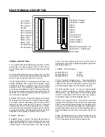
GENERAL DESCRIPTION
The Durant Ambassador 5760X-402 is a count control device
with three count registers - main counter, batch counter and
totalizer. The main counter has one preset and is typically
used to control cut length, fill quantity, or number of pieces/
container. The batch counter counts the number of times the
main counter has cycled and typically represents values
such as: pieces cut, containers filled, cartons made and etc.
The batch preset is useful for signaling or stopping the
process when the desired amount of product is completed.
The totalizer accumulates the total number of counts proc-
essed by the main counter. Its value represents the total
amount of material used by a process or the total number of
pieces processed.
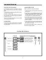
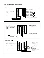
PROGRAMMABLE I/O
One of the unique features of the Ambassador family of
counters is the programmability of the inputs and outputs.
Each of the four inputs can be independently programmed to
perform one of eight functions. The user can also select
which events (counter preset outputs, reset signals, output
control inputs, output timers, and serial commands) cause
each of the three outputs (1 relay and 2 transistor) to pick-up
and drop-out. Any input(s) may be programmed for output
control, however, multiple output control inputs are paralled
into a single output control channel in the unit.
RATE METER
In addition to count/control capabilities, a rate meter is
provided to monitor the speed of the incoming count signal.
This rate feature uses the 1/tau method (event time measure-
ment) and can calculate and scale the rate so that even a low
count speed (.1 Hz) can yield accurate rates in engineering
units (ft/sec, gal/min, etc). The rate feature operates simulta-
neously with the count/control functions.
DISPLAY
All Ambassador Count/Controls are available in green backlit
LCD display and reverse image red LCD display versions.
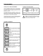
MENU PROGRAMMING
Another unique feature of the Ambassador family of counters
is the menu driven programming. The two line alphanumeric
display prompts programming choices, thus eliminating the
need to remember or look up programming codes. A non-
volatile memory retains programming choices, presets, and
count values while power is removed.
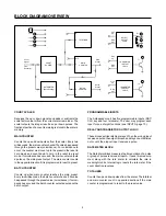
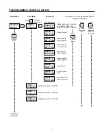
APPLICATION
To better understand the features and capabilities of the
Ambassador, review the simplified block diagram at the top
of the next page and the programming diagrams on pages 6
through 9. Because of the Ambassadors’s versatility, both
programming and wiring decisions must be made before the
counter can be operated. The following sequence of activi-
ties is recommended:
1. Answer the following questions:
What should each count register represent?
What should each output control or do?
What effect should each preset have on the outputs?
What should cause each count register to reset?
Which control signals should affect outputs (resets,
programmable inputs, output timers, etc)?
What engineering units should the rate represent?
2. Go through the programming section and mark the choices
required for the application.
3. Go through the wiring section and lay out the wiring
required. Remember that wiring is affected by program-
ming.
4. Wire and program the counter as determined in steps 2
and 3 above.


