background image

20

SERIAL COMMANDS

  0

Main counter

ACT  123.456 5A (cr)


1

Batch counter

ABT   123456 4B(cr)


2

Totalizer

AT 12345.678 66 (cr)


3

Rate

ART  123.456 60 (cr)


4

Preset 1

AP1  123.456 44 (cr)


6

Batch Preset

APB   123456 47 (cr)

RCD7 is a special command that sends all of the values that
have been specified in the SERIAL OUTPUT menu. The
counter sends values in the order shown above. If the counter
is programmed to send the main count, batch count, and
preset 1, the response might look like this:

ACT  123.456 BT        0 P1  123.456 84(cr)

WP1(nnnnnn) — Write Preset 1
WPB(nnnnnn) — Write Batch Preset

The write preset commands allow a host computer to enter
new preset values. The command must be followed by a 6
digit number (000000  to 999999). All leading zeros must be
supplied. As with keyboard entry, decimal points cannot be
sent to the counter. The counter always displays any decimal
point in the programmed position.

EXAMPLE:  >10WP10005005E(cr)  Sets preset 1 to a value
of 500 on unit 16.

RSC -- Reset Counter
RSB -- Reset Batch Counter
RST -- Reset Totalizer

 The serial reset commands work the same as the reset key
(edge) and reset input (edge) functions. Any outputs which
are programmed to pick-up or drop-out with a counter reset
signal will also respond to the RSC command.

EXAMPLE:  >00RSC48(cr)  Resets the main counter on unit
00.

LAL — Lock All
LPG — Lock Program
UAL — Unlock All
UPG — Unlock Program

The lock and unlock commands allow a host computer to lock
or unlock keyboard programming. The commands are similar
to a lock input function except serial write and programming
commands (WP1, WPB, and ESP) are still allowed.

The counter does not store lock commands when power is
removed. The host must re-issue the desired lock command
after power is re-applied.

Lock inputs are not affected by serial lock commands.  If both
a lock input and a serial lock command are in effect, the user
must remove both locks before programming from the key-
board. The user only needs to remove the lock input for serial
programming.

EXAMPLE:  >5AUPG62(cr)  Cancels a previously issued
Lock Program command to unit 90.

STP — Stop Count
RSM — Resume Count

These commands mimic the stop count input function. When
the counter receives an STP command, all count input pulses
are ignored until the counter receives an RSM command.
These commands are useful when synchronizing serial
counter reset commands.

The counter does not store the serial stop command when
power is removed. The unit will count input pulses when
power is re-applied.

EXAMPLE: >00STP57(cr) Inhibit counts on unit  00

>00RSC48(cr) Reset main counter on unit 00
>00RST59(cr) Reset totalizer on unit 00
>00RSM52(cr) Resume counting on unit 00

OCL — Output Control

Any outputs programmed to pick-up or drop-out with an
output control signal will respond. This command is a one-
shot or edge command. It is the same as turning on an input
that has been programmed for output control.

EXAMPLE:  >01OCL3F(cr)   Sends an output control signal
to unit 01.

RDV — Read Device Value

This command causes the counter to respond with the
product family number, the software version number, the
hardware configuration byte, and the serial ID number.

EXAMPLE COMMAND:  >00RDV4C(cr) Sends RDV com-
mand to unit 00.

For this counter the family number is “1”, the software version
is “1”, and the hardware configuration byte is “5D”. If the serial
ID is set to 00 (00 hexadecimal), the response to the RDV
command will be:

EXAMPLE RESPONSE: A115D003B(cr)

Summary of Contents for Durant AMBASSADOR 57600-402

Page 1: ...oduction 3 Front Panel Features 4 Run Mode Operation 5 Programming 12 Scale Factors 13 Rear Terminal Description 15 Wiring 18 Serial Communications 24 Diagnostics and Troubleshooting 26 Specifications 27 Parts Accessories TABLE OF CONTENTS INSTALLATION AND OPERATION MANUAL Number 57600 902 05 Durant AMBASSADOR SERIES COUNT CONTROL MODELS 57600 402 10 15 VDC 57601 402 115 VAC 57601 452 Red Display ...

Page 2: ...thod eventtimemeasure ment and can calculate and scale the rate so that even a low count speed 1 Hz can yield accurate rates in engineering units ft sec gal min etc The rate feature operates simulta neously with the count control functions DISPLAY All Ambassador Count Controls are available in green backlit LCD display and reverse image red LCD display versions MENU PROGRAMMING Another unique feat...

Page 3: ...set output The main counter counts in the opposite direction if it is programmed to reset to preset BATCH COUNTER Counts up when main counter reaches the main preset Every two milliseconds the batch counter checks if its value has passed through the preset value coincidence If coinci dence has occurred the batch counter outputs a pulse on the batch output PROGRAMMABLE INPUTS The Ambassador unit ha...

Page 4: ...lues Reset Clear Key In the run mode this key can be programmed to reset count values In the preset editing mode this key zeros pre sets that are being changed In the program mode it zeros numeric data that is selected for editing Run Program Key Press this key followed by the Enter key ENT to enter the program mode Pressing this key while in the program mode returns the control to the run mode En...

Page 5: ...nformation to the operator and does not affect the operation of the control If power is removed and restored the unit will power up with the display that was last selected RUN MODE MENUS The keystroke sequence used to access all of the available run mode screens and change preset values is shown in a menu format below CHANGING PRESET VALUES Preset 1 and the batch preset are set as follows 1 Use th...

Page 6: ...urn to the last run mode menu ENTERING THE PROGRAM MODE Press OVERVIEW OF MAIN MENUS Select count mode reset to zero or reset to preset and auto recycle op erations Select the input function to be per formed by each to the four program mable inputs Select normal or reverse logic latched orpulsed pick upanddrop outevents Select the unit I D number baud rate parity and transmission delay Enter count...

Page 7: ...digit HELP programs decimal point SEL selects decimal point position HELP SEL selects decimal point position HELP Select Count Input mode using the UP and DOWN cursors to scroll thru this menu CONTACT ADD SUB SEL PROGRAM COUNT IN SEL RESET TO ZERO SEL RESET TO ZERO RESET TO P1 AUTO CYC DISABLED SEL AUTO CYC DISABLED AUTO CYC P1 0 Select Reset to Zero or Select Reset to Preset Select Auto Cycle Dis...

Page 8: ...G INPUT 1 STOP CNT INPUT 1 LOCK PGM INPUT 2 DISABLED INPUT 3 DISABLED INPUT 4 DISABLED Output Control Reset Counter Edge triggered Reset Counter Level sensitive Reset Batch Edge triggered Reset Totalizer Edge triggered Count Inhibit Lock Program mode Lock Program Preset edit mode Repeated as above for INPUT 1 Repeated as above for INPUT 1 Repeated as above for INPUT 1 PROGRAM OUTPUTS press to retu...

Page 9: ...P1 D0 Drop Outoutput Enter output pulse time XX XX seconds SEL SEL SEL MAIN MENU SUB MENU VIEW MENU EDIT MENU Selection repeats as for P1 above Selection repeats as for P1 above Selection repeats as for P1 above PROGRAM SERIAL PORT Repeats as for RELAY 1 above Repeats as for RELAY 1 above Preset 1 Batch Preset Output Control In Front panel and Remote Counter Rst press to return one menu level pres...

Page 10: ...SKIP or SEND for each data block to be transmitted when requested by the host computer RST KEY DISABLED USER PROGRAM SEL PROGRAM OPTIONS SEL RST KEY DISABLED RST KEY RS C EDG RST KEY RS C LVL RST KEY RS B EDG RST KEY RS T EDG RST KEY RS D EDG USER PROGRAM DEFAULT PROGRAM SEL Define the function of the front panel RST CLR key Reset Counter Edge triggered Reset Counter Level sensitive Reset Batch Ed...

Page 11: ...nals SOLID ST C x2 DIR same as above except counts occur on both edges of input signal for increased resolution RESET TO ZERO the main counter resets to zero when a main counter reset occurs The normal count direction is up and the main counter outputs respond only when counting up RESET TO P1 the main counter resets to the preset value when a main counter reset occurs Preset coincidence oc curs w...

Page 12: ...and transistor output 2 sub menus SERial PORT SER PORT ID enter the desired two digit serial ID number DESCRIPTION OF PROGRAM OPTIONS 00 99 decimal All communications to the control must contain this number in hexadecimal Each unit must have a unique ID BAUD selects the serial port transmit and receive baud rate Allowable rates are 19200 9600 4800 2400 1200 and 300 Version 5 firmware or later To c...

Page 13: ...e the count scaler required to indicate material usage in 1 100 s of feet XXXX XX 100 CS 0 83333 120 Select the XXXX XX position on the counter decimal point menu RATE SCALING The 1 Tau rate meter calculates rate by measuring the time interval between input pulses converting to frequency and multiplying by the rate scaler The rate scaler is user pro grammed to convert the count input pulse frequen...

Page 14: ...DC Common when picked up For maxi mumnoiseimmunity thegroundterminalmustbeconnected to a good earth ground All shielded signal cables should be connected to earth ground or ground on the counter 5 6 and 7 Not Used 8 9 and 10 Relay 1 contacts The relay output consists of oneelectricallyisolatedformCsetofcontacts Theusermust supply power through a contact to the external load The contacts remain in ...

Page 15: ...input signal On input B requires a current sourcing input signal Switch 3 Input A threshold level Off high threshold level use with DC sensors On low threshold level use with mag pickups Turn switch 1 on Switch 4 Input B threshold level Off high threshold level use with dc sensors On low threshold level use with mag pickups Turn switch 2 on Dip switches may be set through an opening on the bottom ...

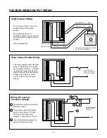
Page 16: ...tact Count Input 1 12 2 3 4 5 6 7 8 9 10 11 13 14 15 16 17 18 19 20 21 22 Dotted lines indicate which inputs may be wired in this manner Typically a separate sensor is used for each input Control inputs terminals 15 18 may be wired in the same manner Use 1 2 amp slow blow fuse Does not include external transducer load Check part number on counter label to verify correct voltage rating 57600 40X 10...

Page 17: ...ed in the same manner Do not connect Term 1 if sensor is powered from another power supply Wire colors shown correspond to Cutler Hammer inductive proximity and photo sensors Dip switches 1 and or 2 ON to select current source mode switches 3 and 4 OFF Current Sourcing Sensor Count Input Current sourcing sensor output The output voltage of this sensor must be between 3 5 and 17 VDC 100 duty cycle ...

Page 18: ...for a single channel encoder All dip switches OFF This wiring example shows the load being controlled from the normally open contacts of Relay 1 Wiring for the normally closed contacts 8 9 would be done in the same manner Wiring for the Relay 2 contacts 5 6 7 is also done in the same manner Load AC or DC Power Source for Load 275 VAC 150 VDC Max Wiring DC Loads to Transistor Outputs 1 12 2 3 4 5 6...

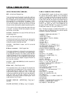
Page 19: ...II code with the RS 485 serial specifi cation and Opto 22 compatible protocol This allows bi directional communications and addressing of multiple con trols on a single two wire communication bus Each unit is individually addressed via a user programmable ID number Up to 100 counters can be connected directly to the bus Interconnect kits and bulk RS 485 communication cable are available see access...

Page 20: ...SERIAL COMMAND RESPONSE FORMAT responds by sending an ASCII N not acknowledged followed by a one character error code and a carriage return Error Codes 00 Power up Error When power is applied to the unit or the program mode is exited the unit performs a power up self test The first valid command received by the unit following the self test is not executed and not acknowledged 10 Lock input is on c...

Page 21: ... store lock commands when power is removed The host must re issue the desired lock command after power is re applied Lock inputs are not affected by serial lock commands If both a lock input and a serial lock command are in effect the user must remove both locks before programming from the key board The user only needs to remove the lock input for serial programming EXAMPLE 5AUPG62 cr Cancels a pr...

Page 22: ... by a two or three digit number representing the desired sub menu see diagram on pages 22 and 23 for sub menu numbers The counter responds by transmitting a number representing the current option selected for a sub menu EXAMPLE COMMAND 00RPI20AD cr Read input 1 selection EXAMPLE RESPONSE A20092 cr Input 1 is disabled SAMPLE COMMUNICATIONS PROGRAM The following BASIC program can be used to demonstr...

Page 23: ...1 102 103 104 105 106 107 108 RESET TO AUTO CYC ZERO P1 DISABLED P1 0 11 12 110 111 120 121 INPUTS PROGRAM INPUT 1 INPUT 2 INPUT 3 INPUT 4 Next item is PROGRAM SER PORT on next page OUT MODE PROGRAM RELAY 1 Repeated as shown above for INPUT 1 Repeated as shown above for INPUT 1 Repeated as shown above for INPUT 1 DISABLED BYP P1 RS C EDG RS C LVL RS B EDG RS T EDG OUT CTRL STOP CNT LOCK PGM LOCK A...

Page 24: ...RATE SER PORT ID BAUD PARITY Tx DELAY 0 002 0 100 SEND SKIP SEND SKIP SEND SKIP SEND SKIP SEND SKIP READ RPI 40 41 42 43 50 51 52 53 54 410 411 412 413 420 421 422 430 431 500 501 530 531 510 511 520 521 540 541 PB SEND SKIP 56 560 561 WRITE WPI PROGRAM OPTIONS END of PROGRAM MODE rolls around to PROGRAM SCALERS menu DISABLED RS C EDG RS C LVL RS B EDG RS T EDG RS D EDG RST KEY PROGRAM LOAD DEF PR...

Page 25: ...ress the front panel reset key This will reset all user programmable options to the factory default settings and rerun all tests 3 If the same error occurs again there is a malfunction within the counter return it to the factory for repair If the counter does not display an error the unit is OK and can be put back in service Before starting the machine again check all preset values and user progra...

Page 26: ...lts peak to peak If it is less the sensor is defective or the target is too far from the sensor or the target is not moving fast enough III Error Message On Display The message ERROR followed by a single digit number on the display indicates that the counter s internal self tests have detected a problem See the self test section of this manual page 24 to determine what caused the problem and how t...

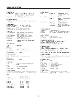
Page 27: ...peed Mode Solid state Contact Inp A Inp B high speed low speed Add Sub 20 kHz 40 Hz Add Add 20 kHz 40 Hz Count Direction 15 kHz 40 Hz Count x 2 Direction 7 5 kHz N A Quadrature 6 5 kHz N A Quadrature x 2 6 5 kHz N A COUNT INPUTS Sink Impedance 4 6k ohms to 5 VDC Voltage high 3 5 to 34 0 low 0 0 to 1 9 VDC Source high Impedance 2 3k ohms to common Voltage high 3 5 to 17 0 VDC 100 duty cycle low 0 0...

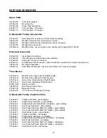
Page 28: ...xxx Medium Duty single channel Shaft Encoder 38151 xxxx Medium Duty quadrature Shaft Encoder 48370 xxxx Heavy Duty single channel Shaft Encoder 48371 xxxx Heavy Duty quadrature Shaft Encoder ES9513 RS Rotary Contactor 39400 400 Zero Speed Vane Pickup 47004 400 Magnetic Pickup 28433 400 30 Tooth Gear for Magnetic Pickup Ambassador Family Count Controls 5760x 400 Totalizer with Rate green display 57...

Page 29: ...mposed upon any person pursuant to the Magnuson Moss WarrantyAct P L 93 637 asnowineffectorasamendedhereafter The warranties and remedies provided for herein are available to Buyer and shall not extend to any other person COMPLIANCE WITH OSHA Eaton offers no warranty and makes no representation that its products comply with the provisions or standards of the Occupational Safety and Health Act of 1...

Page 30: ...Printed in U S A Durant 901 South 12th Street Watertown WI 53094 920 261 4070 800 540 9242 FAX 920 261 9097 ...

Reviews: