2
Installation and electrical connections
DPCT IOM InsTruCTIOn OPeraTIOn Manual
MN124018EN January 2023 www.eaton.com
2. Installation and electrical connections
2.1 Mounting
Carefully unpack the controller and inspect it thoroughly.
The controller should be located as close as is practical
to the engine it controls and shall be within sight of the
engine, preferably ten feet or less.
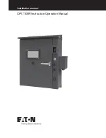
The DPCT controller is designed for wall mounting and
it is recommended to use ½” Grade 5 hardware. For
dimensional and weight data please refer to the respective
data sheet for the Diesel Fire Pump Controller.
The Occupational Health and Safety Administration (OSHA)
recommends that the weight limit for individual lifting be 50
pounds (22.7kg). The final assembled weight of the DPCT
controller depending on selected options could exceed this
value. Therefore, Eaton recommends a two-person lift when
lifting or transferring the controller assembly.
If the assembly is mounted outdoors, it should not be
mounted in direct sunlight. Direct sunlight exposure will risk
damaging the user interface touchscreen.
2.2 Pressure sensor connections
The DPCT is equipped with a pressure sensor to monitor
the fire suppression system water pressure. The controller
is provided with a ½” NPT female system pressure
connection. It is located external to the enclosure on
the right-hand side. The connection should be installed
as per the direction given in the latest revision of NFPA
20, Standard for the Installation of Stationary Pumps for
Fire Protection.
NOTE
Water supply lines to the pressure sensor or pressure
switch must be free of dirt and contamination.
The measured system pressure is displayed on the
user interface touch screen. Specific START and STOP
pressure set points are programmable through the
user interface touchscreen. Refer to Section 5 for
programming instructions.
The maximum operating pressure of the pressure sensor
and internal plumbing components is listed on the
controller nameplate.
2.3 Electrical connections
NOTICE
ALL CONDUIT CONNECTIONS TO THE CONTROLLER
ARE RECOMMENDED TO ENTER THROUGH THE
BOTTOM OR LOWER RIGHT SIDE OF THE ENCLOSURE.
THE ENCLOSURE IS SUPPLIED WITH LABELLING THAT
DIRECTS THE INSTALLER TO THE ENTRY/EXIT LOCATIONS
REQUIRED TO MAINTAIN WARRANTY. REFER TO THE
ASSOICATED DIMENSIONAL DRAWING FOR REFERENCE.
DRILLING HOLES OR INSTALLING CONDUIT ABOVE
THE LEVEL OF THE MICROPROCESSOR BOARD MAY
VOID WARRANTY.
All electrical connections should meet all relevant national
and local electrical codes and standards and follow the wire
sizing guidance supplied inside the controller enclosure.
The controller shall be located or protected in such a
manner so that it will not be damaged by water escaping
from pumps or pump connections.
Current carrying parts of controllers shall be a minimum of
12 inches (305mm) above the floor.
Prior to starting, verify all data on the nameplate such as:
catalog number, AC line voltage and DC battery voltage.
Inspect all electrical connections, components, and wiring
for any visible damage and correct as necessary. Ensure
that all electrical connections are properly tightened before
energizing the controller.
Refer to the appropriate field connection drawing affixed
to the enclosure door, for all wiring information pertaining
to the incoming AC power supply, batteries, and diesel
engine wiring
.
Install required conduit using industry standard methods
and tools.
The incoming 120-240V 50-60Hz AC line voltage connection
is clearly marked L (Line), N (Neutral) and G (Ground), and is
located on the DPCT I/O (Input/Output) Board (port P11).
Terminals 1 through 12, 301 through 304, and 310 through
312 (ports P13, P14, P15, P16, P17 and P18) located on the
DPCT I/O board are for connections to the corresponding
terminals in the diesel engine controller.
Terminals 39 through 49 (port P1) located on the DPCT I/O
board are for connecting a variety of external I/O devices to
the DPCT. These I/O are designed to be used with dry type
contacts (voltage free).
CAUTION
DO NOT APPLY AC VOLTAGE TO TERMINALS 39
THROUGH 49.
Terminals 50 through 73 (ports P2, P3, P4, and P5) located on
the DPCT I/O board are for connection of all the output relay
functions. Terminals 50 through 55 (port P2) can carry 240VAC
maximum at 10 Amperes. Terminals 56 through 73 (ports P3,
P4 and P5) can carry 240VAC maximum at 8 Amperes.
NOTE
All field connections and AC wiring must enter the
enclosure through the lower right sidewall or right side of
the bottom end wall ONLY OTHERWISE WARRANTY IS
VOID. (Refer to the labels affixed inside of the enclosure)
2.3.1 Field Conductor Sizes
Refer to the recommended wire size table supplied inside
of the controller enclosure.


