EATON CORPORATION www.eaton.com
5
Instruction Leaflet IL 33-LGH-3
Effective September 2010
Digitrip Retrofit System for the ITE
LG-3000 (Frameless) Circuit Breaker
Step 3:
Installing the Auxiliary CT Module
A. Assure that the Breaker is in the open position.
Note:
Even with the Breaker in the open position,
there may still be slight tension on the Main
Charging Spring. Use a suitable brace between the
Main Charging Arm and the front Breaker Frame to
prevent the charging spring from releasing. Refer
to the ITE LG-3000 (Frameless) Instruction Manual,
originally supplied with the Breaker, for more
information.
B. Remove and save the hardware securing the
pivot block to the front Breaker Frame.
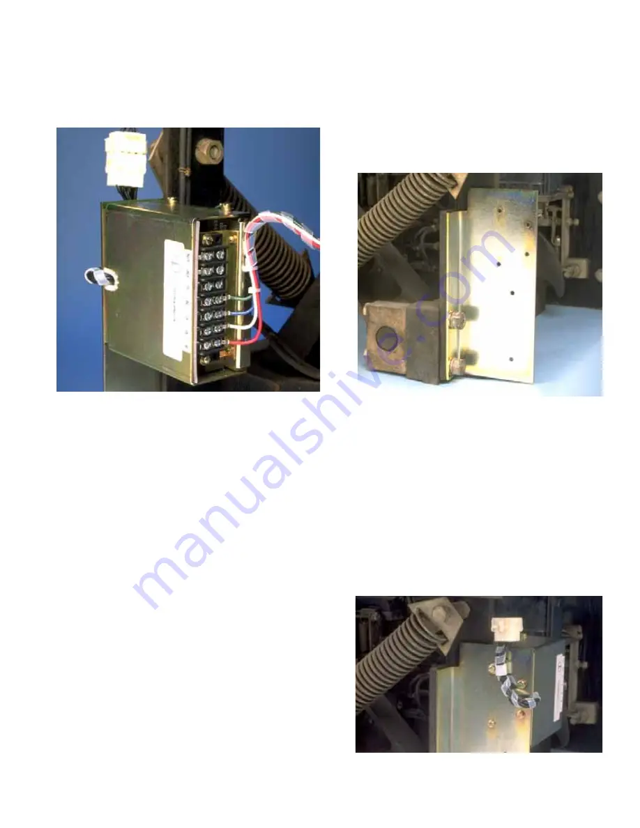
C. Mount the Aux. CT Module Mounting Bracket to
the front Breaker Frame, as shown, using the
original mounting hardware and the (2) .500"
flat washers supplied.
D. Remove the two (2) existing screws from the
back of the Aux. CT Module. Cut away the
grommet from the back of the Aux. CT Module
but leave the grommet in place on the top of the
Module. Align the holes in the back of the Aux.
CT Module with the holes in the Aux. CT
Module Mounting Bracket. Secure the Aux. CT
Module to the bracket, as shown, using the
(2) .190-16 x .500" and (2) .190-16 x .750"
thread cutting screws, (4) lock washers, (4) flat
washers, and (1) nylon wire clamp supplied.
Note that the wire clamp is used to secure the
Aux. CT Module pigtail to the Mounting Bracket.


