6
Instruction Leaflet IL
66A7638H03
Effective December 2010
Instructions for DNP MINT Translator Module
Installation and Use
EATON CORPORATION www.eaton.com
I.L. 66A7638H03
Effective September 2007
6
5.1
DNP RS-485 Network Rx LED
[Green]
The LED will be illuminated whenever the DNP
MINT is receiving content from activity on the
DNP network.
5.2
DNP RS-485 Network Tx LED
[Green]
The LED will be illuminated whenever the DNP
MINT is transmitting on the DNP network.
5.3
INCOM Network Rx LED [Green]
The LED will be illuminated whenever the DNP
MINT is receiving messages from the INCOM
network.
5.4
INCOM Network Tx LED [Green]
The LED will be illuminated whenever the DNP
MINT is transmitting messages on the INCOM
network.
5.5
Status LED [Green]
This indicator will begin flashing after the
module has powered up, its processor has
performed its RAM tests and the microcontroller
is executing instructions. The flashing rate is
approximately 1 second ON / 1 second OFF.
This indicator will flash at a rate of
approximately 5 times a second during an auto
learn dip switch detection sequence (see
Section
7.0
).
After accepting a configuration request, the DNP
MINT will hold this LED ON for approximately
2.5 seconds.
5.6
INCOM 100
Ω
Ω
Termination DIP
Switch (SW1)
This switch should be moved to the “ON”
position only when it is the last unit in a chain of
units or if it is a single unit.
5.7
DNP RS-485 Baud Rate DIP
Switch (SW2)
To set the data transfer rate for the DNP
network, two switches in dip switch SW2
(SW2-2 and SW2-3) should be moved to either
the “CLOSE” or the “OPEN” position based on
the rate required. Refer to
Table 4
. SW2-1 is
for DNP MINT configuration.
Baud
SW2-1
SW2-2
SW2-3
1200
X
CLOSE
CLOSE
9600
X
OPEN
CLOSE
19200
X
CLOSE
OPEN
Table 4: RS-485 Baud Rate Switches
5.8
DNP Diagnostics Enable
(Configuration Mode) Switch
(SW2)
To configure the DNP access settings and the
INCOM device access settings within the DNP
MINT, the SW2-1 dip switch must be moved to
the “OPEN” position. Refer to
Table 5
.
Normally, this switch is in the “CLOSE”
position. Changing this dip switch
automatically forces a reset of the DNP MINT.
Baud
SW2-1
SW2-2
SW2-3
Configure
OPEN
X
X
Normal
CLOSE
X
X
Table 5: RS-485 Diagnostics Enable
(Configuration Mode) Switch
5.9
DNP/RS-485 121
Ω
Ω
Termination
DIP Switch (SW3)
This switch should be set to the “ON” position
only when it is the last unit in a chain or if it is
the only outstation device on the DNP Network.
6.0
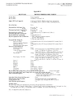
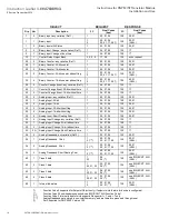
DNP V3.00 DEVICE PROFILE
The DNP V3.00 device profile for the DNP
MINT is listed in
Appendix A
.
.


