10
Instruction Leaflet IL
66A7638H03
Effective December 2010
Instructions for DNP MINT Translator Module
Installation and Use
EATON CORPORATION www.eaton.com
I.L. 66A7638H03
Effective September 2007
10
Appendix B
configuration tables, enter the
respective Configuration Tag for that selection.
For INCOM devices without a specific pre-
defined configuration, select the most
appropriate Generic Device or Generic Trip Unit
configuration after review of IL 17384.)
A device’s tag value of FFFF
16
will remove the
device from the DNP MINT, which will also
force the device’s “DNP Address” and “INCOM
Address”
settings
to
FFFF
16
,
an
unused/non-configured virtual DNP slave device
state.
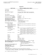
These DNP MINT counter object points (
Table
7
) are returned to the DNP master in response to
a Read (Function Code 01) Counter (Group 20)
Object request using Variations 2 or 6 (16-bit
Binary Counter with or without Flag), Qualifier
00, 01 or 06 (no Preindex, 8-bit, 16-bit start and
stop ranges or no ranges) during both
configuration and normal (run-time) modes,
with normal mode dependent on a valid DNP
MINT’s “DNP Address” setting. Note that
points 0 through 5 are read only DNP MINT
variables.
8.2
Configuration Of Summary Table
Settings
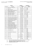
The DNP MINT contains a summary table (see
Table 8
) providing various configuration
settings for overall DNP MINT operation. It
also contains a summary table (see
Table 9
) for
each INCOM device providing various
configuration settings required by the DNP
MINT for interaction pertaining to/with the
device. This information can only be read and
written from a DNP master device when the
DNP MINT is placed in the configuration mode
(see
Section 5.8
). The information is returned
from the DNP MINT in response to a Read
(Function Code 01) Counter (Group 20) Object
request using Variations 2 or 6 (16-bit Binary
Counter with or without Flag), Qualifier 01 (no
Preindex, 16-bit start and stop ranges or no
ranges). The most significant byte of the range
fields is used to distinguish which summary
table is being accessed, 0 (00
16
) pertaining to the
DNP MINT summary table and 1 (01
16
) through
16 (10
16
) pertaining to each of the 16 devices.
The least significant byte of the range fields
defines the counters being accessed and start at
128 (80
16
) so that the DNP MINT summary table
does not overlap the pre-defined table described
in
Section 8.1
. Also note that these counters
will not be returned along with the pre-defined
table counters with a Qualifier 06 (no Preindex,
no ranges) read request.
Summary information is entered into the DNP
MINT using a Write (Function Code 02)
Counter (Group 20) Object request using
Variation 6 (16-bit Binary Counter without
Flag), Qualifier 01 (no Preindex, 16-bit start and
stop ranges or no ranges). The DNP MINT will
only accept the request when the counter range
field pertains to one and only one DNP MINT or
device summary table. Also, when selecting the
DNP MINT summary table counters, the request
cannot be intermixed with the pre-defined
counters described in
Section 8.1
.
8.2.1
DNP Master Station Address
The DNP Master Station Address setting is the
DNP source address value the DNP MINT will
accept in a request message and thus return as
the destination address in the corresponding
response message. It is also applied as the
destination address in a generated unsolicited
message. A valid setting is 0000
16
through
FFEF
16
. The DNP MINT will not accept a write
request with an invalid setting. This value is set
in the DNP MINT summary table and applies to
all DNP MINT messages (DNP MINT counters
and its 16 devices).


